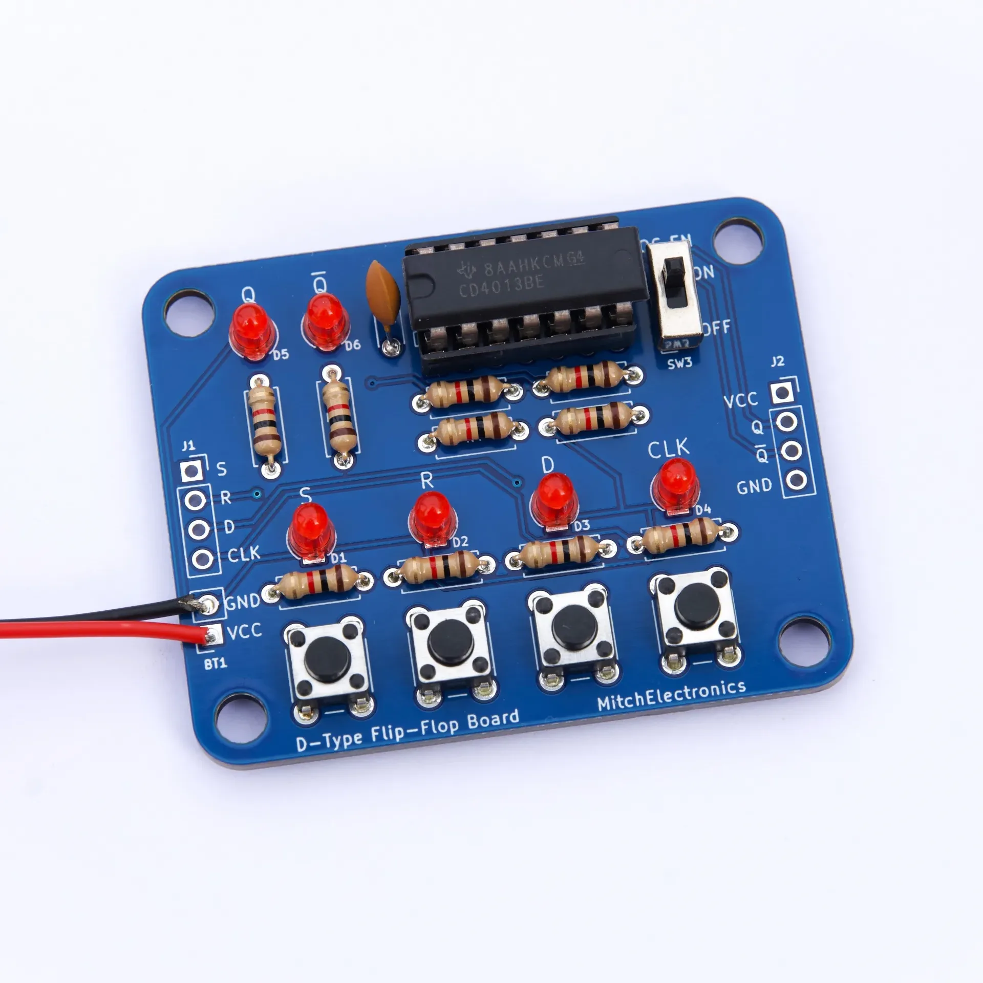
4013 D-Type Flip-Flop Board

£4.99

The 4013 D-Type Flip Flop Board lets you experiment with the 4013 dual flip flop IC, how to convert them into a toggle, and much more! Ideal for education and soldering practice.

Availability: 3 in stock (can be backordered) SKU: 4013-FLIPFLOP Categories: , , Tags: , , , , , , ,

Description

4013 D-Type Flip Flop Board

The 4013 D-Type Flip Flop kit is designed to let you experiment with the famous 4013 IC, which incorporates two independent flip flops. Each of these flip-flops not only has two complementary outputs, a clock input, and data input, but also a set and reset input that can be used to force the state of the flip-flop to a particular value.

Even though the 4013 IC (which is a part of the 4000 series of logic devices), has two independent flip-flops, the kit only uses one of these flip-flops, with the other being entirely used. This is to keep the circuit simple and reduce the number of components on the PCB.

The board integrates a special switch, SW3, which allows for connecting the D input to the complementary output /Q, which will turn the flip-flop into a toggle latch. When in toggle mode, pushing the clock input, the internal state of the flip-flop will switch to the opposite value

Instructions / Documentation

Product specifics

  • Component Count: 25
  • Battery Powered: Yes
  • Operating Voltage: 3V – 9V
  • Operating Frequency: N/A
  • Dimensions (PCB): 54mm x 43mm
  • Mounting Holes: Yes – 4 x M4 (46mm x 35mm)
  • Prebuilt: No – Kit form
  • Batteries Not Included

Included in this kit

  • 1 x 14-DIP Socket
  • 1 x 4013 IC
  • 1 x 100nF Capacitor
  • 10 x 1K Resistor
  • 6 x 3mm Red LEDs
  • 4 x Tactile Switches
  • 1 x SPST Switch
  • 1 x PP3 Connector

Applications

The 4013 D-Type Flip Flop kit is an ideal teaching tool for learning how latches work, connecting them together, and toggle functions. As the kit requires assembly, the 4013 D-Type Flip Flop kit is also suitable for solder practice, giving students two opportunities for education in a single kit. Pin contacts on the side of the board allow for further expansion with other circuits, thus enabling for more complex projects.

Notes

Note that product specifics such as output frequency depend on the tolerance of the components. The numbers provided here are an approximation only. Also take note that the estimated delivery is not guaranteed (unless special delivery is chosen) and free delivery has a maximum waiting time of two weeks. Any product that is returned which is built using lead solder is ineligible for a refund.

All parts sold by MitchElectronics are compliant with RoHS and REACH directives which ensure that they can be used in commercial environments as well as complying with environmental laws. Watch the video below to learn more about RoHS compliance and why it may be important for your next DIY project!
For full terms and conditions for all MitchElectronics products, click the button below.

Additional information

Weight 0.015 kg

Reviews

There are no reviews yet.


Only logged in customers who have purchased this product may leave a review.