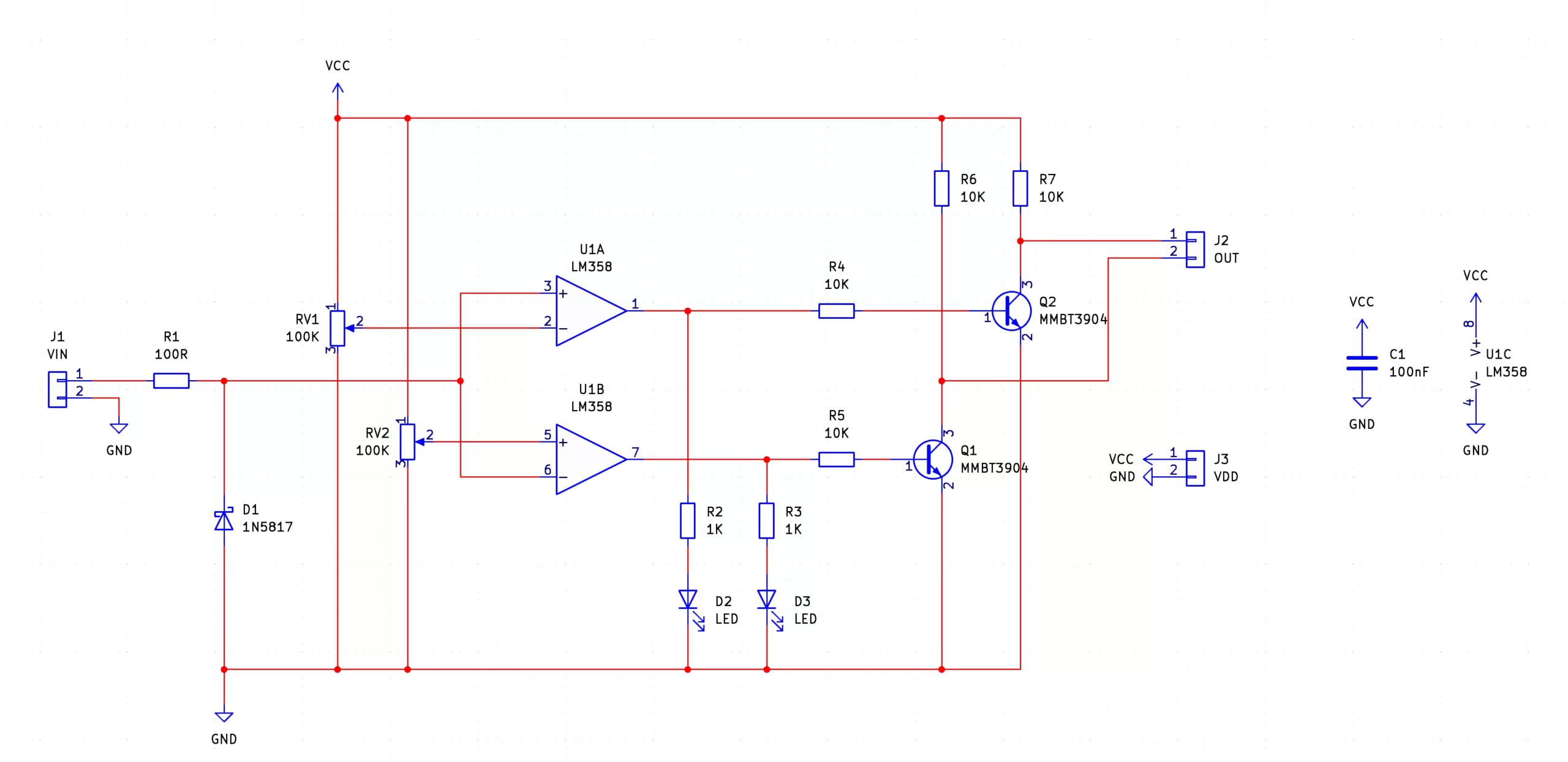
The Hi Low Detector SMD Trainer is a dual op-amp circuit that compares an input voltage to two different voltage levels; one representing too high and one representing too low. The two potentiometers represent the different high and low voltage levels, and the two on-board LEDs light up when either level is detected. The output of the Hi Low Detector is inverted, meaning that the Hi output switches low when the input is too high, and the low output switches low when the input is too low.
Besides the obvious use of SMD training, the Hi Low Detector can be used in applications where a signal needs to be maintained at some level. For example, a greenhouse can use a temperature sensor to open windows if it gets too hot, but what about if it gets too cold? With the Hi Low Detector, the low output could be used to control a heater, thereby giving a greenhouse complete control over its temperature.
Another fantastic use of the Hi Low Detector is as a water tower controller. If the water level in a tank becomes too great, a safety valve can be controlled to drain some of the water. If the water level becomes too low, the same circuit can control a pump to refill water.
| Component | PCB Reference | Quantity | Looks Like |
|---|---|---|---|
| LM358 Op-Amp IC SOIC8 | U1 | 1 |  |
| 100nF 0805 Capacitor | C1 | 1 |  |
| 100R 0805 Resistor | R1 | 1 |  |
| 1K 0805 Resistor | R2, R3 | 2 |  |
| 10K 0805 Resistor | R4, R5, R6, R7 | 4 |  |
| 100K SMD Potentiometer | RV1, RV2 | 2 |  |
| 0805 Red LED | D2, D3 | 2 |  |
| 1N5817 Diode SMD | D1 | 1 |  |
| MMBT3904 NPN Transistor | Q1, Q2 | 2 |  |
| Red Wire | VCC | 1 |  |
| Green Wire | VIN | 1 |  |
| Blue Wire | OUT | 2 |  |
| Black Wire | GND | 2 |  |


To learn more about how to solder electronic components, download the Electronics Construction Manual free using the button below
Electronics Construction Manual
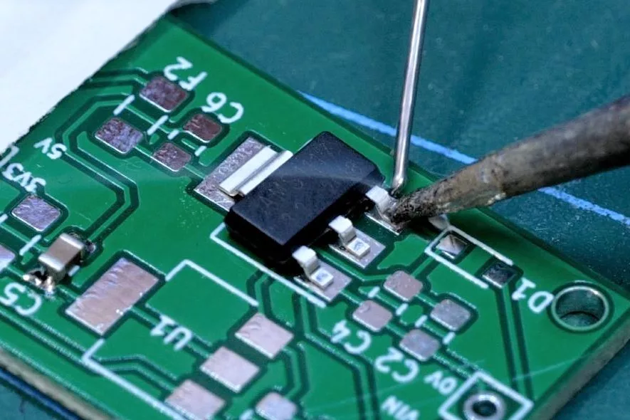
When soldering components, it is essential that you do so in a particular order, so that it is easy to add components and get to their legs. Generally, you always start with the smaller components (such as resistors and capacitors), before moving onto the larget parts (potentiometers and ICs).
Soldering Guide
To help keep the board stable when soldering, you can download a free STL model of a basic jig that can be 3D printed with all common 3D printers. Watch out for the mounting hole pins as they may be vulnerable to snapping if using a low infill density, low wall thickness, or thick layer heights. Additionally, do not use hot air to solder the PCB when using the jig as you will melt the jig.
Coming Soon...

(+44) 7516 323 698

27 Willow Way, Meon Vale, CV37 8FT, United Kingdom

Co. House No. 14068499


