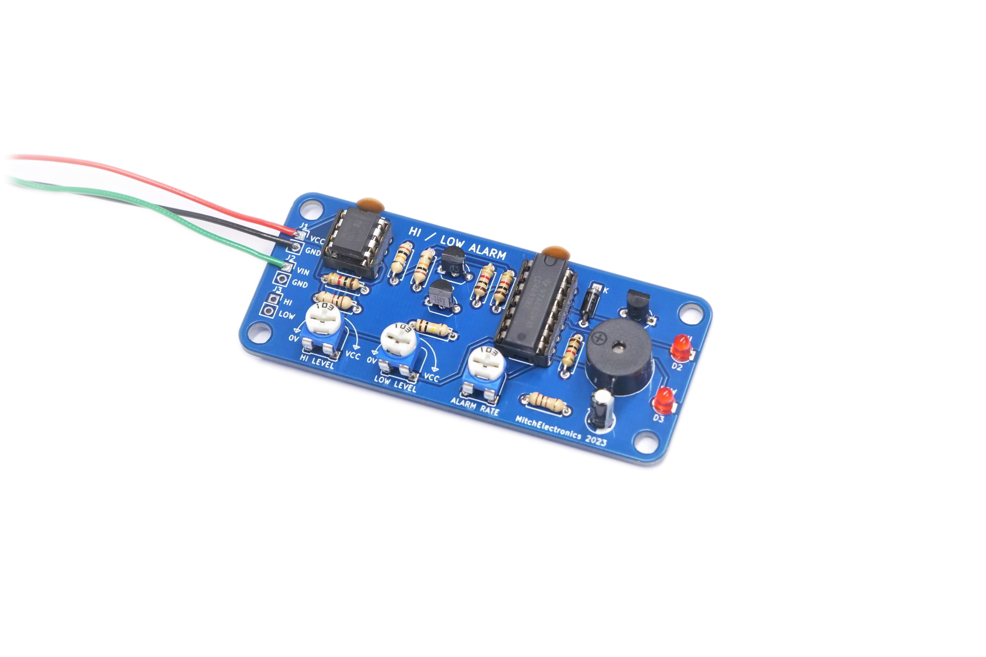
The Hi/Low Alarm Kit is an alarm circuit that sounds a beeper when a measured voltage becomes too small or too large. The detection point for both the low and high voltage levels can be set using the two onboard potentiometers, and the rate of beeping can also be changed with another potentiometer.
This kit uses an LM358 as a dual comparator to detect both low and high conditions, and a 4093 quad NAND Schmitt trigger provides tone generation and gating.
This kit has two primary uses, with the first being the detection of dangerous operating conditions, and the second being the detection of sensor readings out of range.
In the case of dangerous operating conditions, this kit can be used to monitor the output voltage of a power supply, and sound an alarm if that voltage becomes too small or too large (such as in battery charging applications).
In the case of sensor readings, this kit can be used to control devices that react to changes in sensor outputs. For example, a water level monitor could use this to sound an alarm if a water tank needs filling or automatically power a pump to refill the tank with water.
The Hi/Low Alarm consists of three main circuit sub-blocks; a comparator stage, an RTL NOR gate, and a gated tone generator.
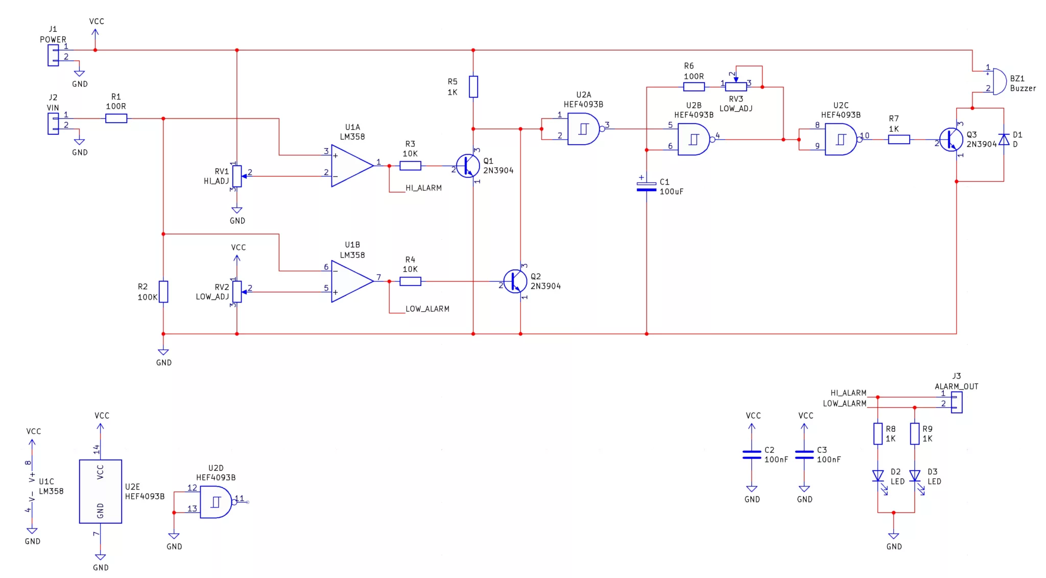
To start, an external voltage is fed into VIN (J2), which passes through a potential divider consisting of R1 and R2. The extremely low value of R1 compared to R2 (100Ω << 100KΩ) means that the voltage across R2 is almost identical to the voltage being fed into VIN. The purpose of R1 is to provide some series limiting the current that could otherwise damage the circuit should a fault occur on the VIN input.
This voltage across R2 (which is the same as the voltage on VIN), is fed into two different comparators, U1A, and U1B, which each have their own separate potentiometer.
U1A is configured as a non-inverting comparator which will output a logical 1 when the voltage present on VIN is larger than the voltage set by the potentiometer RV1. This op-amp indicates a “voltage high” condition, and is also connected to the LED D2.
U1B is configured as an inverting comparator that will output a logical 1 when the voltage present at VIN is smaller than the voltage set by the potentiometer RV2. This op-amp indicates a “voltage low” condition, and is also connected to the LED D1.
Each comparator has an additional pull-down transistor on their outputs, and the combination of R5, Q1, and Q2 makes an RTL NOR gate. Simply put, if any of the comparators outputs a logical 1, the voltage at the input of U2A will be pulled down to ground (i.e., 0V).
If the input to U2A is pulled to ground, the output of U2A will switch to 1 as it is configured as an inverter. The second NAND gate, U2B, is configured as a tone generator with R6, RV3, and C1 (see inverting Schmitt trigger oscillator). If the output of U2A is a logical 1, the tone generator U2B outputs a square wave whose frequency is dependent on the resistance of RV3.
Finally, the output of the tone generator is connected to another NAND gate configured as an inverter (U2C), and this, in turn, powers a buzzer controlled by Q3. The diode D1 prevents the buzzer from generating large negative voltages that can damage the transistor Q3.
| Component | PCB Reference | Quantity | Looks Like |
|---|---|---|---|
| 8 DIP Socket | U1 | 1 |  |
| 14 DIP Socket | U2 | 1 |  |
| LM358 Op-Amp IC | U1 | 1 |  |
| 4093 Quad NAND IC | U2 | 1 |  |
| 100R Resistor | R1, R6 | 2 |  |
| 1K Resistor | R5, R7, R8, R9 | 4 |  |
| 10K Resistor | R3, R4 | 2 |  |
| 100K Resistor | R2 | 1 |  |
| 10K Potentiometer | RV1, RV2, RV3 | 3 |  |
| 100nF Ceramic Disc Capacitor | C2, C3 | 2 |  |
| 100uF Electrolytic Capacitor | C1 | 1 | 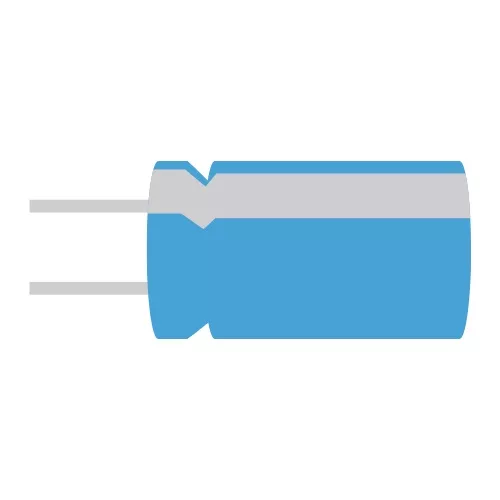 |
| 3mm Red LED | D2, D3 | 2 | 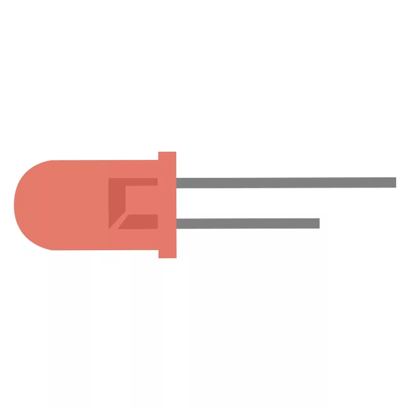 |
| 1N5817 Schottky Diode | D1 | 1 |  |
| 2N3904 NPN Transistor | Q1, Q2, Q3 | 3 | 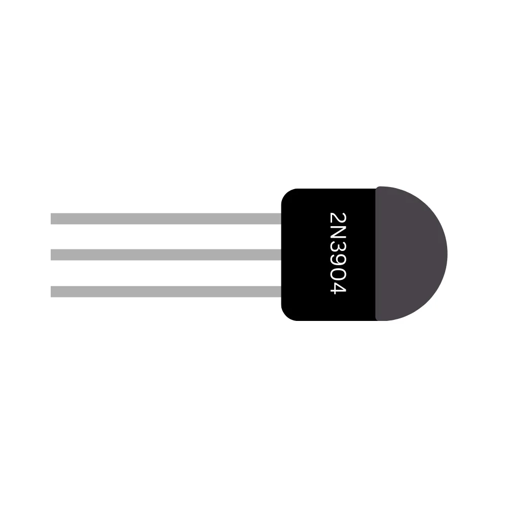 |
| Active Magnetic Buzzer | BZ1 | 1 | 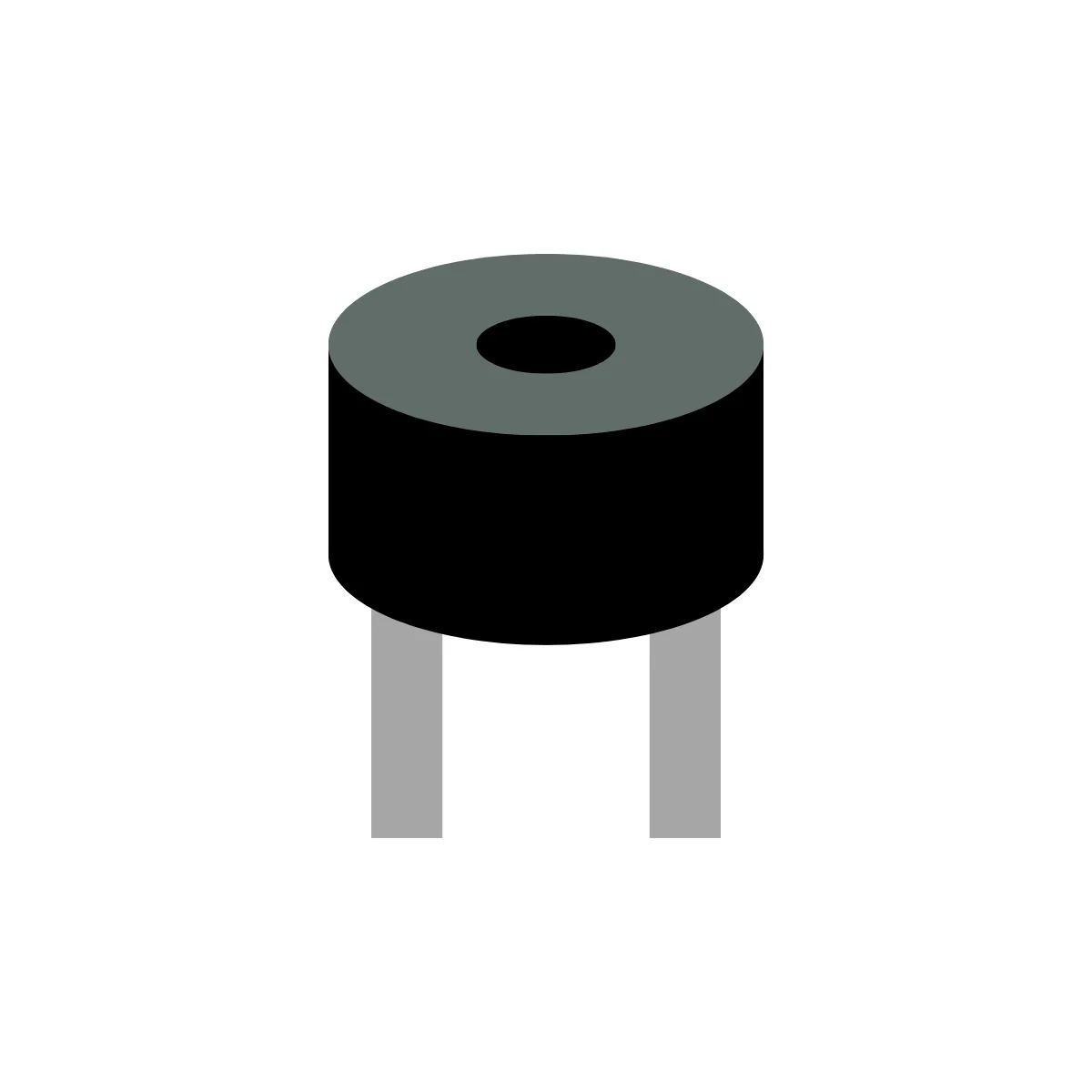 |
| Red Wrire | J1 | 1 |  |
| Green Wire | J2 | 1 |  |
| Black Wire | J1, J2 | 2 |  |

The Hi/Low Alarm kit can be used to monitor the voltage output of a power supply and warn nearby users if the power supply voltage drifts too much. This can be extremely important in applications where circuits cannot tolerate large changes in supply voltage (such as microcontrollers and microprocessors), as well as circuits that are under test (such as in laboratory conditions).
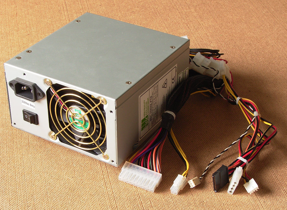
The Hi/Low Alarm kit can be used to monitor the voltage output of a power supply and warn nearby users if the power supply voltage drifts too much. This can be extremely important in applications where circuits cannot tolerate large changes in supply voltage (such as microcontrollers and microprocessors), as well as circuits that are under test (such as in laboratory conditions).


To learn more about how to solder electronic components, download the Electronics Construction Manual free using the button below
Electronics Construction Manual
When soldering components, it is essential that you do so in a particular order, so that it is easy to add components and get to their legs. Generally, you always start with the smaller components (such as resistors and capacitors), before moving onto the larget parts (potentiometers and ICs).
Soldering Guide
The separate Hi and Low outputs allow for connecting other circuits
Consider using a relay driver to automatically control devices

(+44) 7516 323 698

27 Willow Way, Meon Vale, CV37 8FT, United Kingdom

Co. House No. 14068499