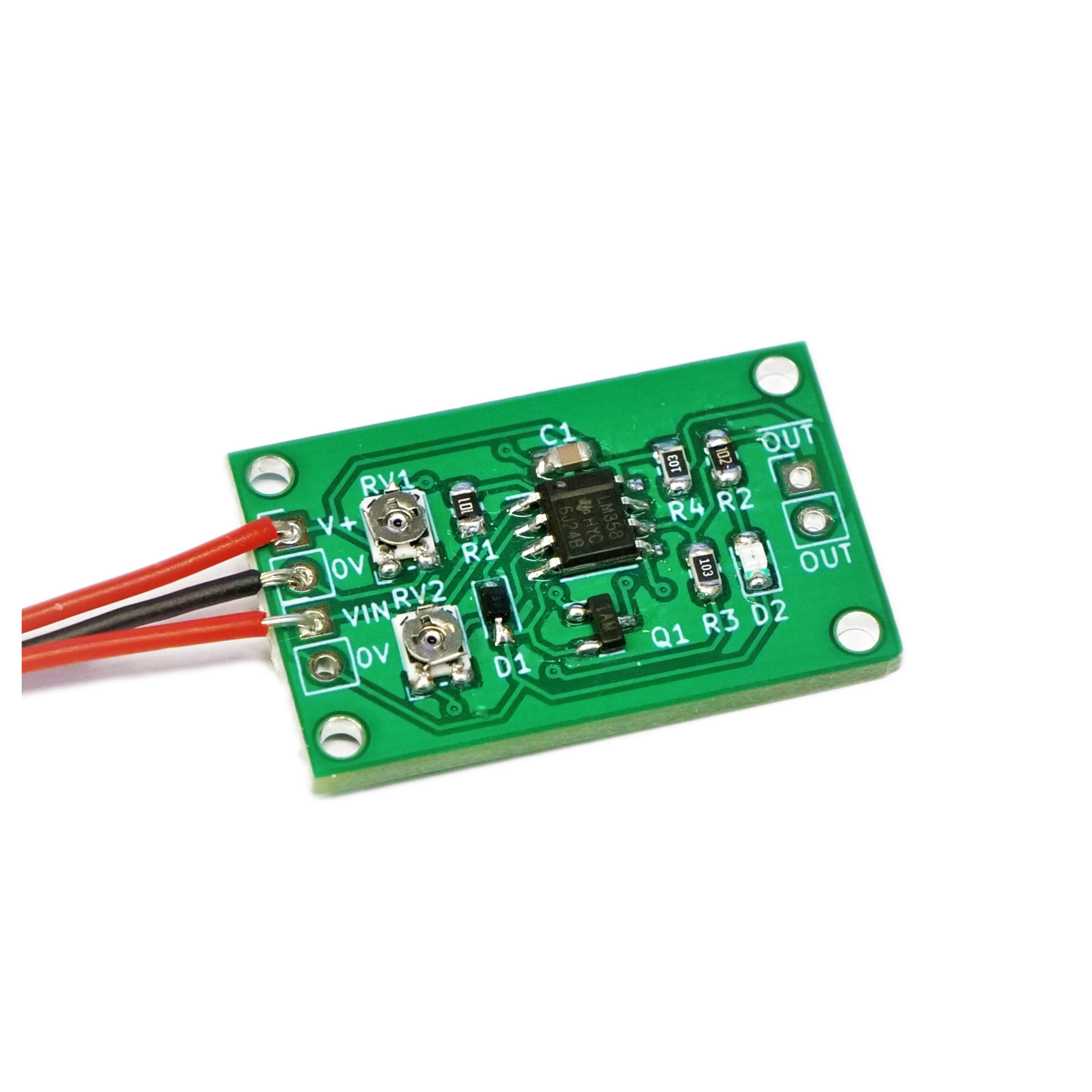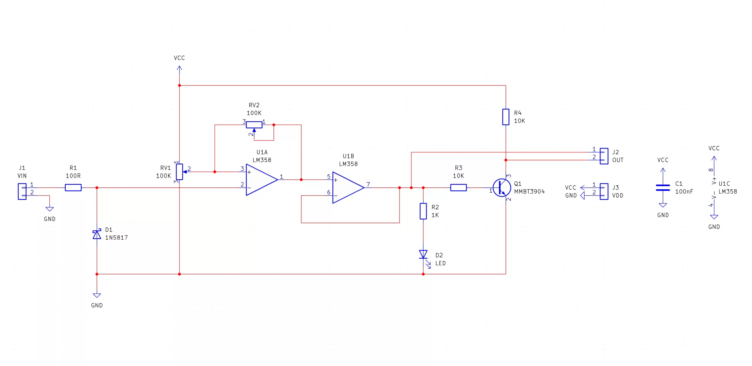
The Schmitt Trigger SMD Trainer kit lets you build a fully adjustable Schmitt trigger, including the hysteresis point and the size of the hysteresis. The Schmitt trigger itself, U1A, is actually configured as an inverting Schmitt trigger such that a signal going beyond the upper threshold will actually result in a low output. The on-board LED indicates the output of this Schmitt trigger, so the LED is also inverting. The output of the module, however, has an extra inverter, so that you an choose between a non-inverting and inverting Schmitt trigger.
Besides the obvious use of SMD training, the Schmitt Trigger SMD Trainer can be used for any application where hysteresis is needed. For example, a heating control in a room requires hysteresis, otherwise, tiny fluctuations in the ambient temperature could result in the heating rapidly being switched on and off. This rapid switching can damage equipment, and as such, a Schmitt trigger can prevent this by only changing the output after some margin has been passed.
Another excellent use for Schmitt triggers is in RC oscillators. If the input to the Schmitt trigger is connected to a capacitor, and a feedback resistor from the inverting output is connected to the input, then the hysteresis results in a perfect square wave oscillation, whose frequency is dependent on the resistor and capacitor size (such that larger values result in a slower oscillator).
| Component | PCB Reference | Quantity | Looks Like |
|---|---|---|---|
| LM358 Op-Amp IC SOIC8 | U1 | 1 |  |
| 100nF 0805 Capacitor | C1 | 1 |  |
| 100R 0805 Resistor | R1 | 1 |  |
| 1K 0805 Resistor | R2 | 1 |  |
| 10K 0805 Resistor | R3, R4 | 2 |  |
| 100K SMD Potentiometer | RV1, RV2 | 2 |  |
| 0805 Red LED | D2 | 1 |  |
| 1N5817 Diode SMD | D1 | 1 |  |
| MMBT3904 NPN Transistor | Q1 | 1 |  |
| Red Wire | VCC | 1 |  |
| Green Wire | VIN | 1 |  |
| Blue Wire | OUT | 1 |  |
| Black Wire | GND | 2 |  |


To learn more about how to solder electronic components, download the Electronics Construction Manual free using the button below
Electronics Construction Manual
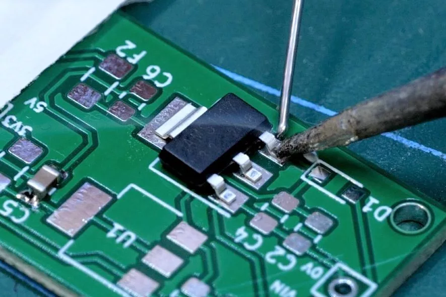
When soldering components, it is essential that you do so in a particular order, so that it is easy to add components and get to their legs. Generally, you always start with the smaller components (such as resistors and capacitors), before moving onto the larget parts (potentiometers and ICs).
Soldering Guide
To help keep the board stable when soldering, you can download a free STL model of a basic jig that can be 3D printed with all common 3D printers. Watch out for the mounting hole pins as they may be vulnerable to snapping if using a low infill density, low wall thickness, or thick layer heights. Additionally, do not use hot air to solder the PCB when using the jig as you will melt the jig.
Coming Soon...

(+44) 7516 323 698

27 Willow Way, Meon Vale, CV37 8FT, United Kingdom

Co. House No. 14068499