In electronics it is sometimes required to have a signal that consistently creates a continuous pulse (like the second hand on a clock which ticks every second). Examples of where this would be useful would include:
- Digital clock (to track time)
- Computers (the CPU needs to be triggered by pulses)
- Most digital systems (usually require a central clock that synchronises all parts)
A circuit which produces a pulse every so often is called an oscillator, and once powered, the output of an oscillator will turn on and off, and once this cycle has been completed it repeats itself indefinitely (so long as there is power). But how is an oscillator made? How do you get some components to keep on pulsing? In this kit, you will be creating a two-transistor oscillator which uses two transistors and a few other components to create an oscillator that generates a few pulses every second so that it flashes (that is why it is called a flasher).
As this circuit is astable it is difficult to explain unless some initial conditions are stated first. For the initial conditions:
- VCC=9V
- Q1 has just turned on and Q2 is on
- C1 positive plate was 9V and has just been discharged to 0V through Q1
- C1 negative plate is 0.7V
- C2 positive plate is 9V and C2 negative plate is 0.7V
With Q1 being turned on the positive plate on C1 is suddenly connected to ground (through Q1). Therefore the voltage on the positive plate becomes 0V (and the LED D1 will turn on). Due to capacitive coupling C1 will attempt to keep the voltage across the two plates the same as before (which was 9V-0.7V = 8.3V). Therefore the negative plate drops to a voltage of -8.3V.
The negative plate of C1 is connected in parallel to the base of Q2. Because the base-emitter voltage of a bipolar transistor can never be greater than 0.7V the voltage on the negative plate of C1 can therefore never be greater than 0.7V (but it can be less!). The same applies to C2 and Q1.
When the negative plate of C1 drops to -8.3V Q2 will turn off hard (this means that it will happen really fast like slamming a door). When Q2 turns off the positive plate of C2 is no longer connected to 0V and therefore quickly charges to 9V (this also results in D2 turning off). In this state, Q1 stays on because the negative plate of C2 is 0.7V and Q2 stays off because the negative plate of C1 is less than 0.7V.
This state does not stay around for long. The negative plate of C1 is also connected to 9V through the resistor R2 which means that the voltage on the negative plate begins to rise. Eventually, the voltage on the negative plate will rise to 0.7V and the circuit changes into the opposite state.
As the negative plate on C1 is now 0.7V Q2 will turn on. When this happens the positive plate of C2 will be connected to 0V and due to capacitive coupling, the negative plate on C2 will drop to -8.3V. This results in Q1 turning off very quickly and D1 turning off. At the same time, the positive plate of C1 will quickly charge to 9V.
Again like before this state does not stay around for long! The negative plate of C2 is connected to 9V through R3 and therefore the voltage on the negative plate begins to rise.
Eventually, the voltage on the negative plate of C2 will reach 0.7V and because the base of Q1 is connected to the negative plate of C2, Q1 will quickly turn on. This entire cycle keeps repeating indefinitely.
| Component | PCB Reference | Quantity | Looks Like |
|---|---|---|---|
| 2N3904 NPN Transistor | Q1, Q2 | 2 |  |
| 680R Resistor | R1 - R4 | 2 | 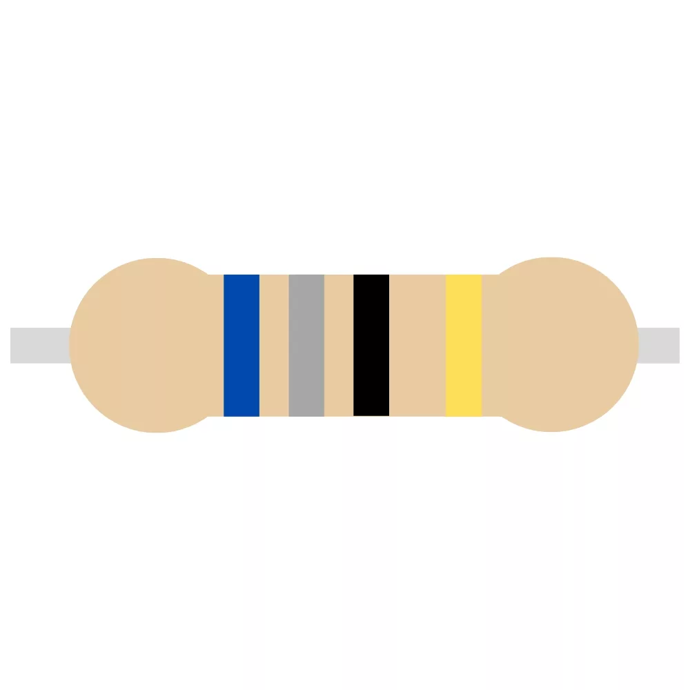 |
| 5.6K Resistor | R2 - R3 | 2 | 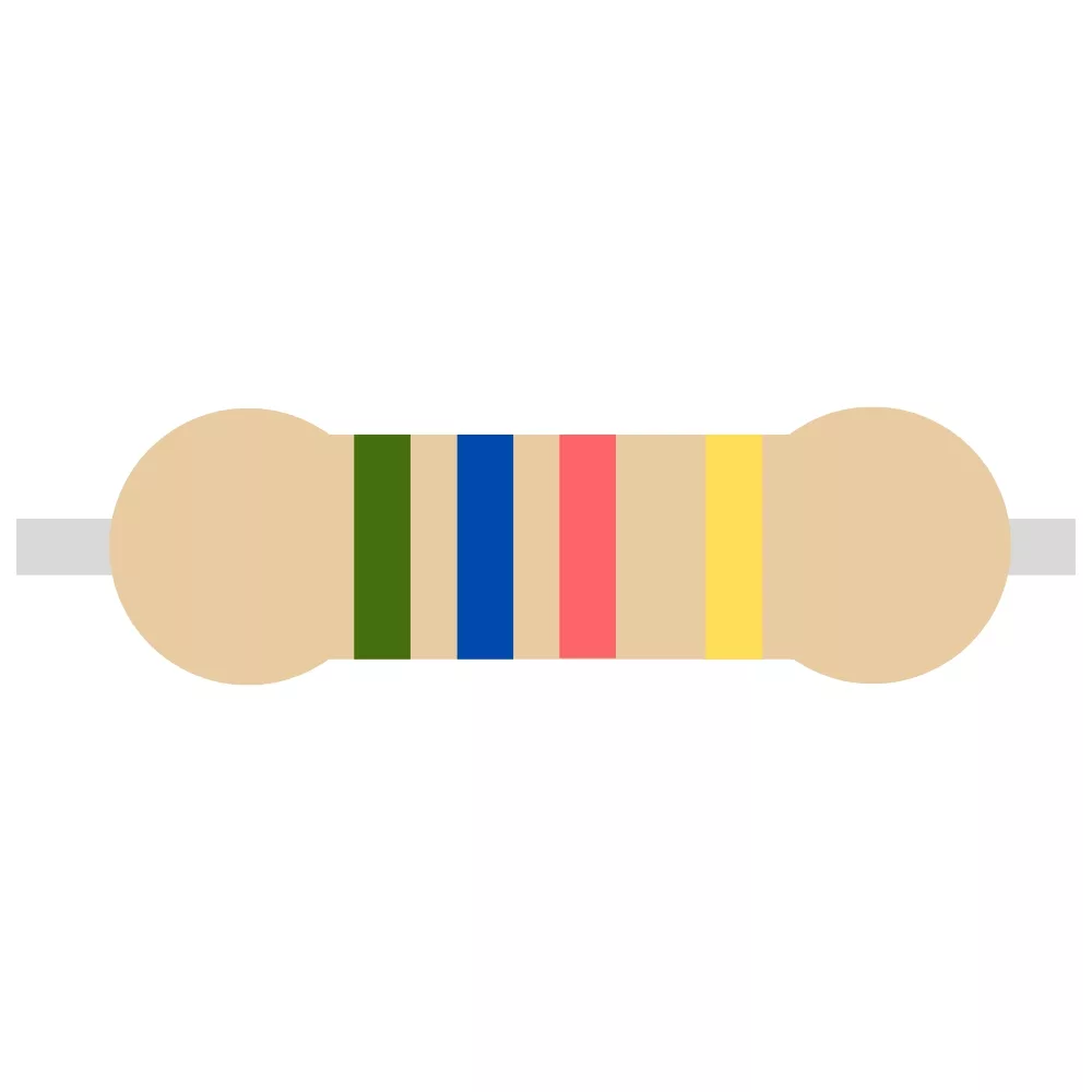 |
| 100uF Electrolytic Capacitor | C1, C2 | 2 |  |
| 3mm Red LED | D1 - D2 | 2 | 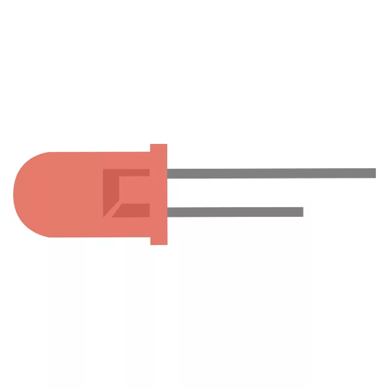 |
| PP3 Battery Connector | J1 | 1 | 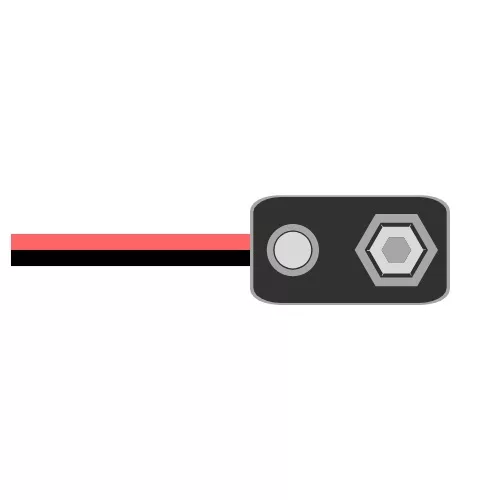 |
The transistor flasher can be used as a clock source for other digital circuits. However, a wire would need to be soldered to the appropriate pad, and the clock output would likely need an output amplifier to create a strong clock signal that swings between the supply voltage and ground.
You can use the transistor flasher to mimic warning lights found at level crossings. Simply provide power to the flasher when a train approaches a crossing, and then turn off the flasher when the train leaves. You can use a relay to control the power to the transistor flasher.


To learn more about how to solder electronic components, download the Electronics Construction Manual free using the button below
Electronics Construction Manual
When soldering components, it is essential that you do so in a particular order, so that it is easy to add components and get to their legs. Generally, you always start with the smaller components (such as resistors and capacitors), before moving onto the larget parts (potentiometers and ICs).
Soldering Guide
Change the value of the capacitors and resistors to adjust the frequency of oscillation
You can remove the capacitors and turn the transistor flasher into an SR latch!

(+44) 7516 323 698

27 Willow Way, Meon Vale, CV37 8FT, United Kingdom

Co. House No. 14068499