Pulse width modulation involves taking a square wave and changing the duty cycle of the wave to convey information. But this explanation is too complex for those who do not know what PWM actually is or have never used PWM signals. So let's start with the basics, the duty cycle!
The graph below shows a square wave with a frequency of f (the actual value does not matter). Two times are shown, Ton and Toff. Ton is the time for which the wave is at its maximum and Toff is the time for which the wave is at its minimum. The time period, t, of the wave is Ton + Toff.
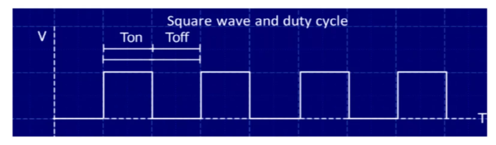
Now the frequency is determined by the time period so therefore the frequency is also dependent on the Ton and Toff values. But realise one thing, the frequency is determined by the sum of Toff and Ton and NOT the individual values.
This means that the frequency can be kept the same BUT the values of Ton and Toff can be changed. This is the basics of PWM and now a new term comes to play, duty cycle!
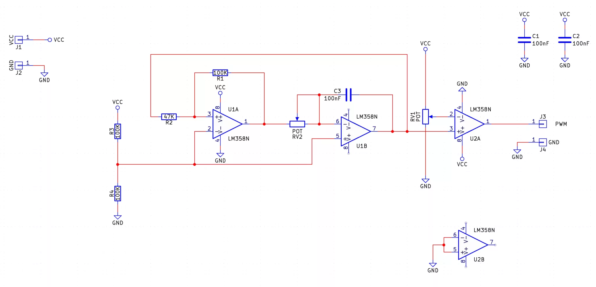
The core of the PWM Generator is a triangle wave generator which is fed into a comparator as shown in the simplified diagram below.
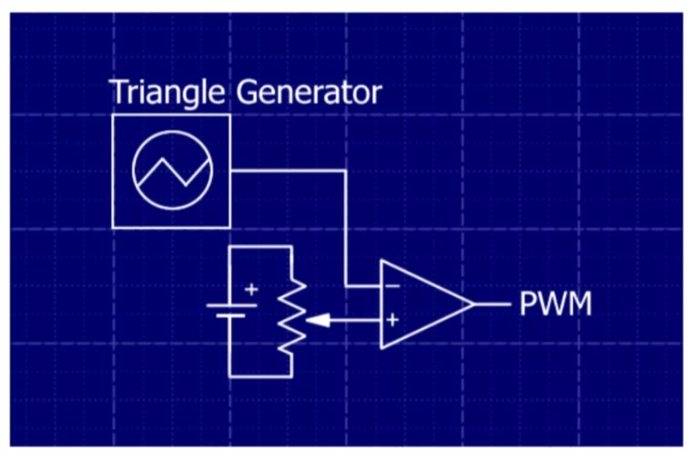
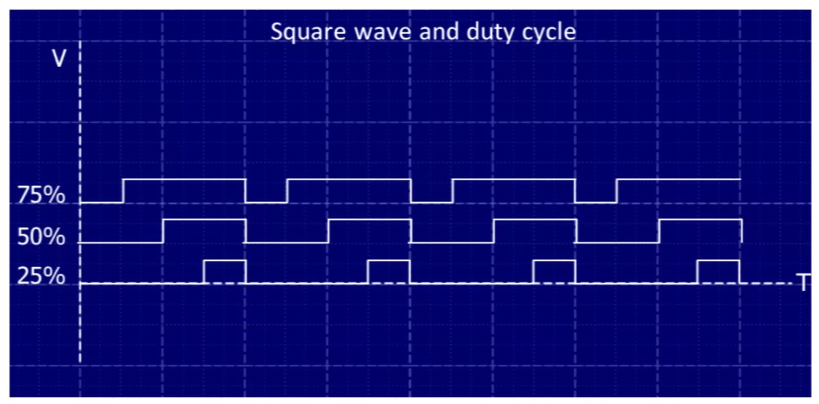
The potentiometer sets the PWM duty cycle by feeding a voltage into the positive pin of the comparator while the triangle oscillator provides the comparative voltage to create a square wave. This can be seen in the graph below more clearly.
In the graph above, the red line represents the voltage being created by the potentiometer RV1, and after a few seconds the potentiometer is turned to output a lower voltage (as shown by the drop in the red line). This lower voltage from the potentiometer output will result in a smaller duty cycle.
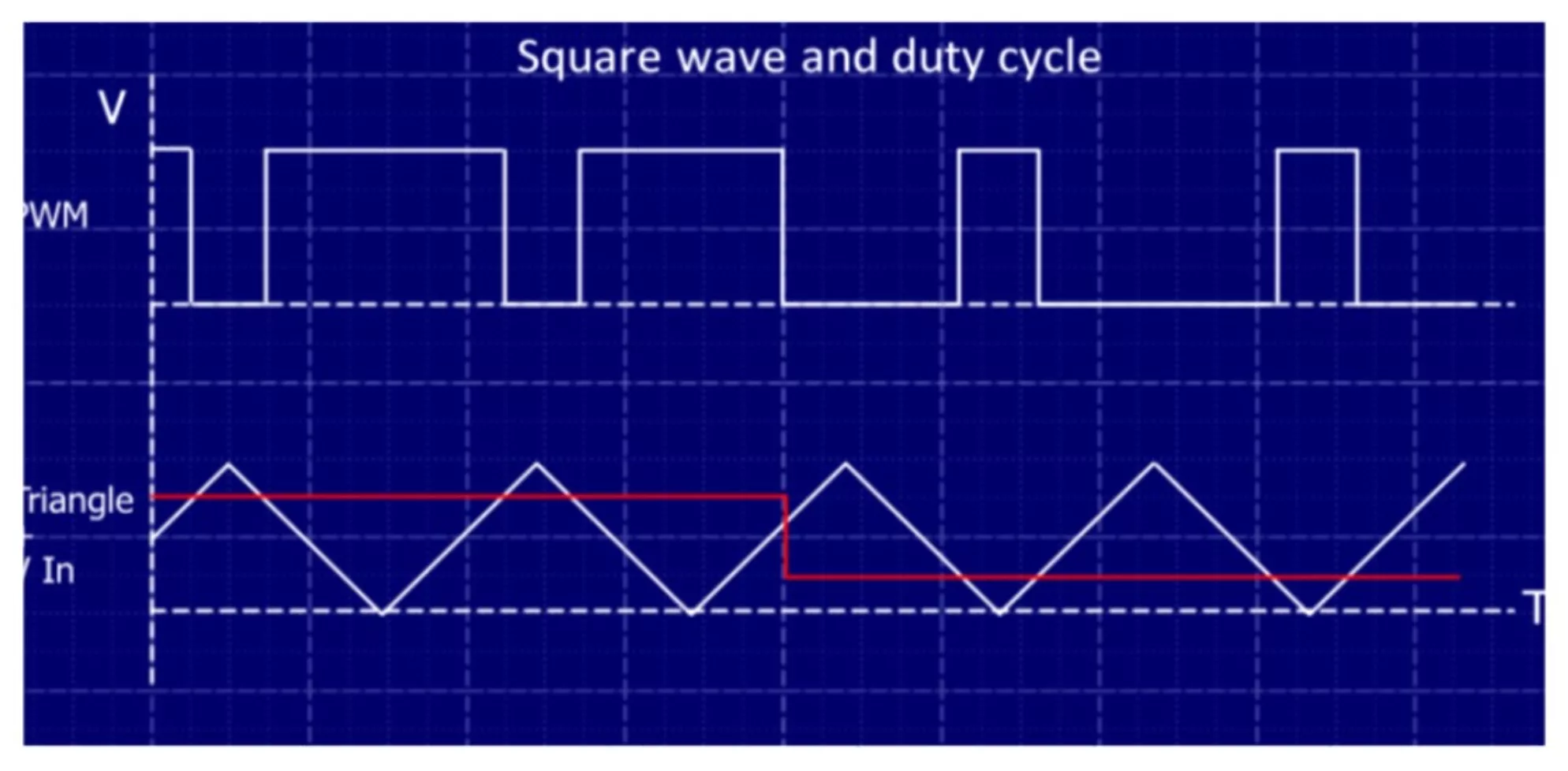
If the triangle wave is larger than the potentiometer voltage the comparator outputs a low voltage. This is because V- is larger than V+. If the triangle wave is smaller than the potentiometer voltage then the comparator will output a high voltage because V+ is larger than V-. That's it! Nothing else to it!
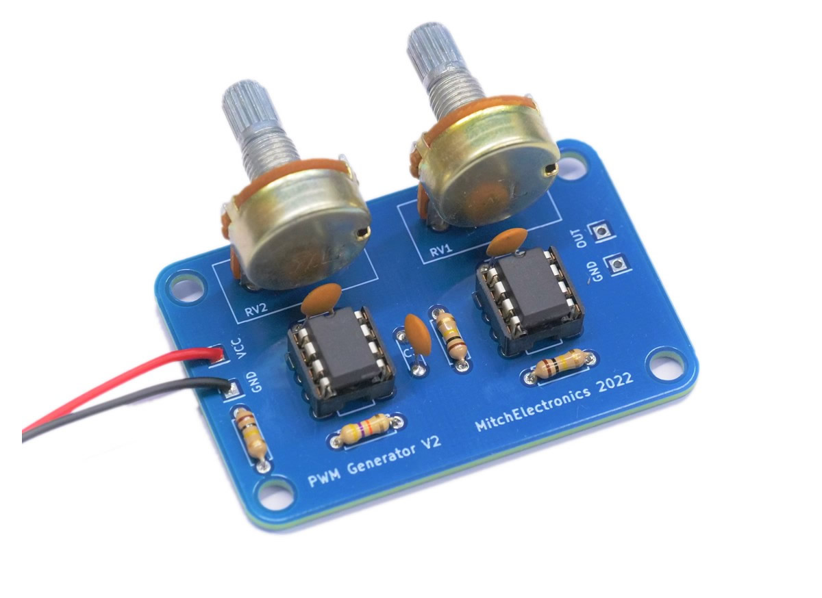
The PWM Generator not only has a potentiometer to adjust the duty cycle but also has a second potentiometer to adjust the frequency (RV2). Adjusting the frequency potentiometer changes the frequency of the triangle generator and thus changes the output frequency of the PWM signal.
| Component | PCB Reference | Quantity | Looks Like |
|---|---|---|---|
| 8 DIP Socket | U1, U2 | 2 |  |
| LM358 Dual Op-Amp IC | U1, U2 | 2 |  |
| 100nF Ceramic Disc Capacitor | C1, C2, C3 | 3 |  |
| 47K Resistor | R2 | 1 |  |
| 100K Resistor | R1, R3, R4 | 3 | 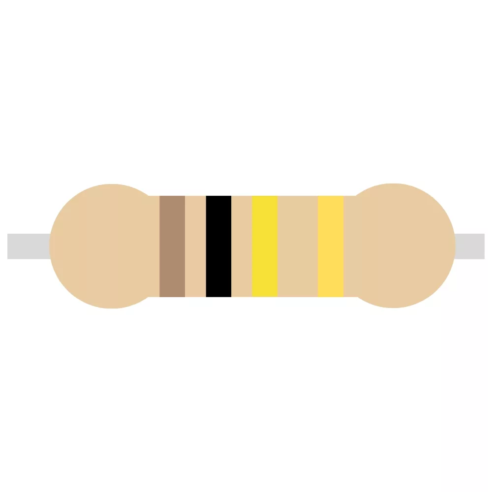 |
| 100K Linear Potentiometer | RV1, RV2 | 2 | 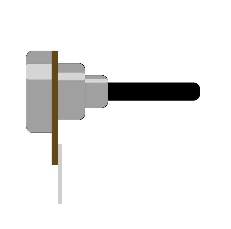 |
| Red Wrire | VCC | 1 |  |
| Blue Wire | PWM OUT | 1 |  |
| Black Wire | GND | 2 |  |
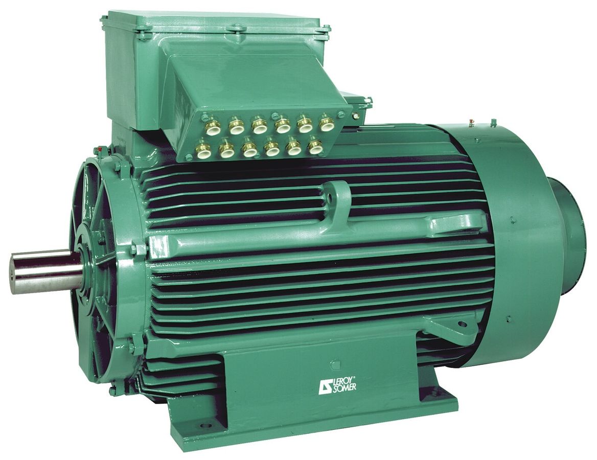
One excellent use for PWM signals is controlling motors without using linear devices (such as voltage regulators and transistors in their active region). Not only does the PWM signal result in an average voltage output (which directly adjusts the speed of the motor), but the fast switching reduces energy losses in the switching device (such as a large MOSFET).
Just as PWM signals can be used to adjust the speed of a motor, they can also be used to adjust the brightness of an LED by turning an LED on and off quickly. If an output switching transistor is used to provide power to LEDs, the PWM signal will adjust the LED brightness, and just like in the motor controller the switching device will experience very little energy waste.

PWM signals are not only excellent for controlling power to devices, but they also produce some interesting sounds. We all know what a square wave sounds like (anyone who has used an ancient games console will know this sound), but PWM square waves have an interesting saw-tooth-like component to them. If this kit replaces RV1 with an external exponential converter (Google this and 1V/Octave Keyboards), you can make a pretty snazzy sound system!

To learn more about how to solder electronic components, download the Electronics Construction Manual free using the button below
Electronics Construction Manual
When soldering components, it is essential that you do so in a particular order, so that it is easy to add components and get to their legs. Generally, you always start with the smaller components (such as resistors and capacitors), before moving onto the larget parts (potentiometers and ICs).
Soldering Guide
If combined with a few external circuits, this can be converted into a basic switch-mode power supply! We won't tell you how, but a hint is to think about how you can use negative feedback from the output 😉
Connecting a resistor ladder network to the input can turn this PWM generator into a digitally-controlled PWM source
You can use this kit to control micro servos commonly found in RC projects. They require a pulsed input, but these are PWM signals representing analogue values!

(+44) 7516 323 698

27 Willow Way, Meon Vale, CV37 8FT, United Kingdom

Co. House No. 14068499