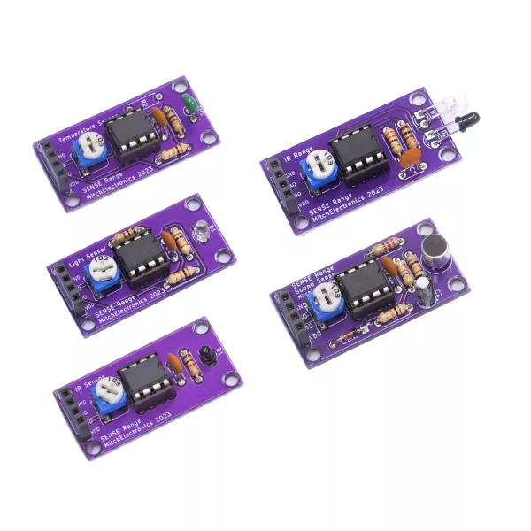
The SENSE Range are electronic kits that let you build your own module with sensing capabilities. Each module has the exact same dimensions, pin-out, and hole location so that modules can be interchanged depending on what needs detecting. For example, the Sound Sense is capable of detecting sound, while the Temp Sense uses a thermistor to detect the ambient temperature.
Unlike other sensing modules on the market, the simplicity of the MitchElectronics Sense Range makes them easy to modify, use in other circuits, and build. At the same time, the standardised 40mm x 20mm dimension is very easy to work with when creating enclosures and mounting a Sense board.
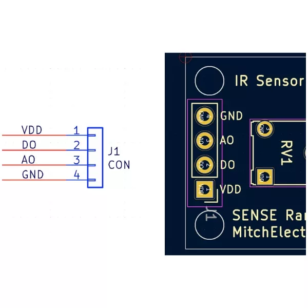
To make using the Sense Range as easy as possible, all Sense kits have a four pin connector that is identical for each device. Two of these pins are for providing power (VCC and 0V), and the other two are one digital output (that switches between VCC and 0V), and analogue output, which varies depending on the signal being sensed. For example, the Sound Sense produces an analogue signal whose amplitude increases with sound volume, while the Temp Sense produces a voltage that directly relates to temperature.
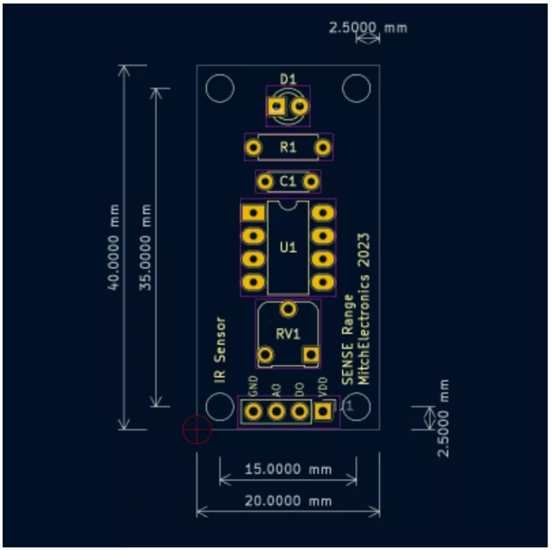
To make sure that using the Sense Range is as simple as possible, all dimensions, hole sizes, and positions are identical across all modules. By doing so, modules can be swapped around without needing to change enclosures, screws, or mountings. At the same time, this standardisation also allows for modules to be stacked in frames which can also be convenient
The standard size for all kits is 40mm x 20mm, M2 holes (2mm diameter), a hole separation of 35mm x 15mm, and a hole edge spacing of 2.5mm.
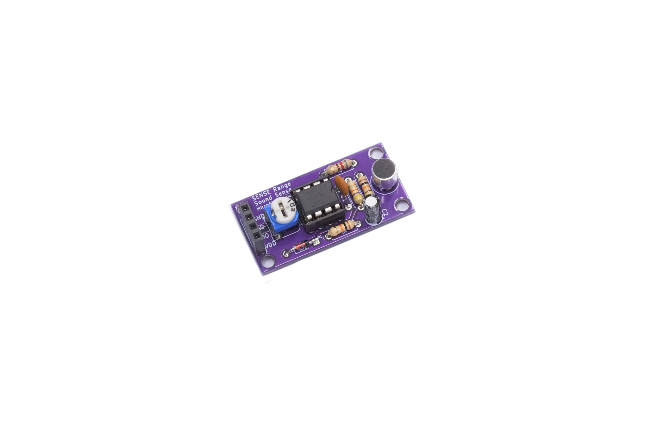
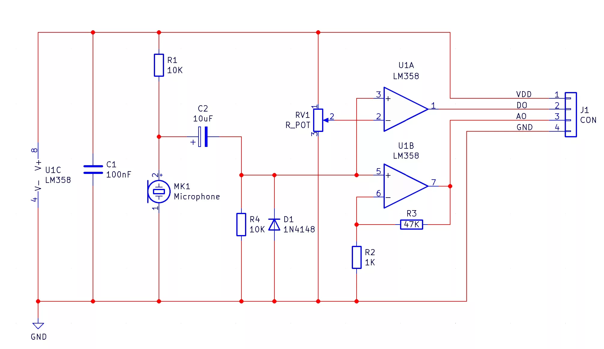
The Sound Sense comprises of an electret microphone (MK1), a comparator (U1A), and a non-inverting amplifier (U1B).
Electret microphones integrate a small Field Effect Transistor (FET) with a gate that is capacitively coupled to a diaphragm. Sound waves that hit the diaphragm cause it to deform in shape, and this results in a change in capacitance. This change in capacitance, in turn, adjusts how much current the FET conducts, thereby converting an acoustic wave into a changing electrical signal. The electret microphone has a 10KΩ pull-up resistor to provide power to the internal FET, and the resulting combination of the resistor and microphone makes a potential divider, whereby louder audio signals result in a smaller voltage across the microphone (because its resistance falls with an increase in volume).
In the presence of no sound, the voltage across the electret microphone is approximately VCC, and this is problematic for trying to detect audio signals. To remove this DC voltage, we use a coupling capacitor (C2) to extract AC voltages only. Therefore, only voltages that change over time can pass, meaning that converted audio waves can pass through C2, but not the stead voltage from the power supply.
This varying audio voltage is then fed into both op-amps, U1A and U1B, which are configured as a comparator and a non-inverting amplifier, respectively. You may notice that there is a diode in reverse bias mode, D1. The purpose of this diode is to remove any negative voltage that may build up from the microphone because negative voltages (with respect to the op-amp negative supply pin), cause the op-amp to become confused and produce unexpected outputs.
The comparator (U1A), has its negative input connected to a potentiometer, which produces a voltage between VCC and 0V depending on its position. If the voltage across R1 is greater than the voltage from the potentiometer, the output of the comparator switches to VCC, indicating that the sound level is greater than the trigger level defined by the potentiometer. If the voltage across R1 is lower than the voltage from the potentiometer, the output of the comparator switches to 0V, indicating that the sound level is lower than the trigger level defined by the potentiometer. The output of the comparator is digital, and can be used to determine if the microphone has detected a minimum level of sound.
The non-inverting amplifier (U1B) has two feedback resistors, R2 and R3, which result in a gain of approximately 50, and this is used to amplify the weak signal produced by the microphone. This output is analogue, and can be used to measure the amount of sound, but remember that the negative component of the sound wave has been removed, so it won’t preserve the quality of the detected audio!
| Component | PCB Reference | Quantity | Looks Like |
|---|---|---|---|
| 8 DIP Socket | U1 | 1 |  |
| LM358 Dual Op-Amp IC | U1 | 1 |  |
| 1K Resistor | R2 | 1 |  |
| 10K Resistor | R1, R4 | 2 |  |
| 47K Resistor | R3 | 1 |  |
| 10K Potentiometer | RV1 | 1 |  |
| 100nF Ceramic Capacitors | C1 | 1 |  |
| 10uF Electrolytic Capacitor | C2 | 1 |  |
| 1N4148 Diode | D1 | 1 |  |
| Electret Microphone | MK1 | 1 |  |
| 4-Way Socket | J1 | 1 |  |

One such use for the Light Sense is as a trigger device for an alarm circuit. At night, when all the lights in a home are turned off, this module can stand guard looking for the tell-tale signs of a burglar looking for your hard-earned cash. The moment a torch light hits the sensor, the digital output can send a signal to an alarm system, and from there, can either set off a sounder, or even text you a message.

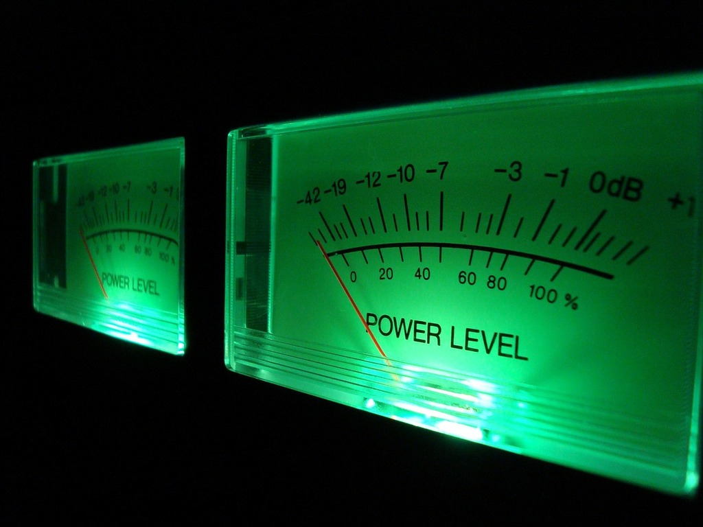
VU Meters are devices that convert audio signals into a visual signal, and are very common in music equipment. While the Sound Sense itself cannot be used as a VU Meter, it certainly can be attached to the input of one, showing the current audio level.
This can be useful especially when recording musical instruments as audio signals that are too strong will clip, and a VU meter can help identify if an audio signal is too strong.
The small size of the Sound Sense makes it possible to turn into a spying device. While the audio quality of the output is not great for music, it is perfectly acceptable for listening into conversations, and connecting the Sound Sense to an audio transmitter can definitely be used to snoop. Connecting the Sound Sense to a Bluetooth transceiver can even allow for a spy device to transmit over Bluetooth.


To learn more about how to solder electronic components, download the Electronics Construction Manual free using the button below
Electronics Construction Manual
When soldering components, it is essential that you do so in a particular order, so that it is easy to add components and get to their legs. Generally, you always start with the smaller components (such as resistors and capacitors), before moving onto the larget parts (potentiometers and ICs).
Soldering Guide
Feeling brave? Consider using different resistors
Can be done to change the sensitivity of the amplifier and microphone

(+44) 7516 323 698

27 Willow Way, Meon Vale, CV37 8FT, United Kingdom

Co. House No. 14068499