The 555 timer IC is arguably one of the most famous integrated circuits that have ever been manufactured. The 555 is such a popular chip that despite having been invented in 1972 it is still produced in the millions each year to this day.
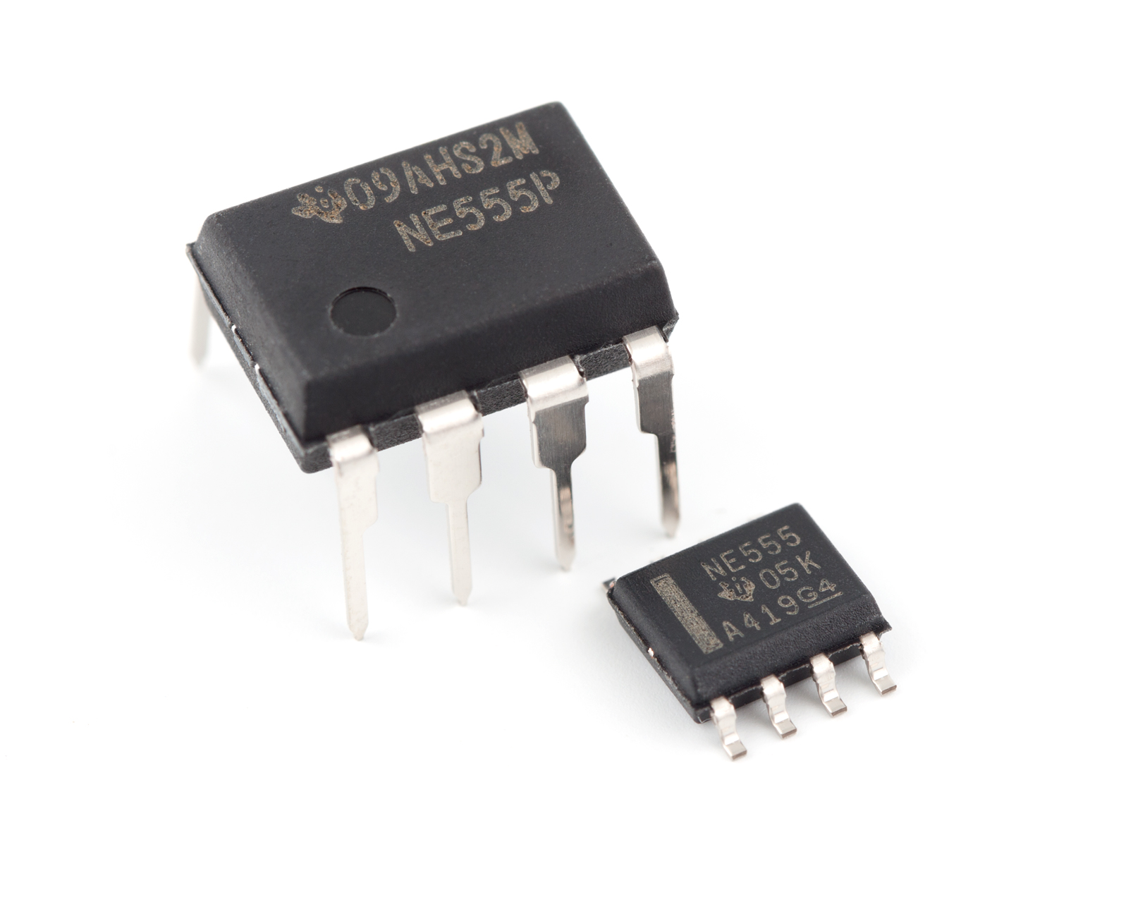
Ever since the first 555 timer, many variations have been designed such as the 556 which includes two 555 timers on the same chip, CMOS versions that use less power, and SMD varieties that allow the 555 to be used on the smallest PCBs.
As the name suggests, the 555 timer is primarily designed as a timer IC which can be used to either produce a constant square wave (astable mode), or a one-shot square signal (monostable mode).
However, the 555 can also be used to do many other things, such as a digital modulator, a latch, and a PWM generator. All of these functions can be realised with the use of external components and clever circuit routing.
The 555 timer used to be a staple in many circuits, but its used in modern electronics is not as obvious. Many low-cost electronics devices from the far-east will often use them (such as relay controls and timers).
The popularity of the 555 timer in the past also sees it in older electronic systems that are still in use. If these circuits fail, a new 555 can replace it!
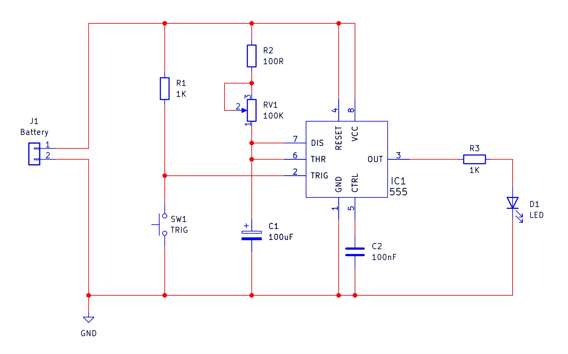
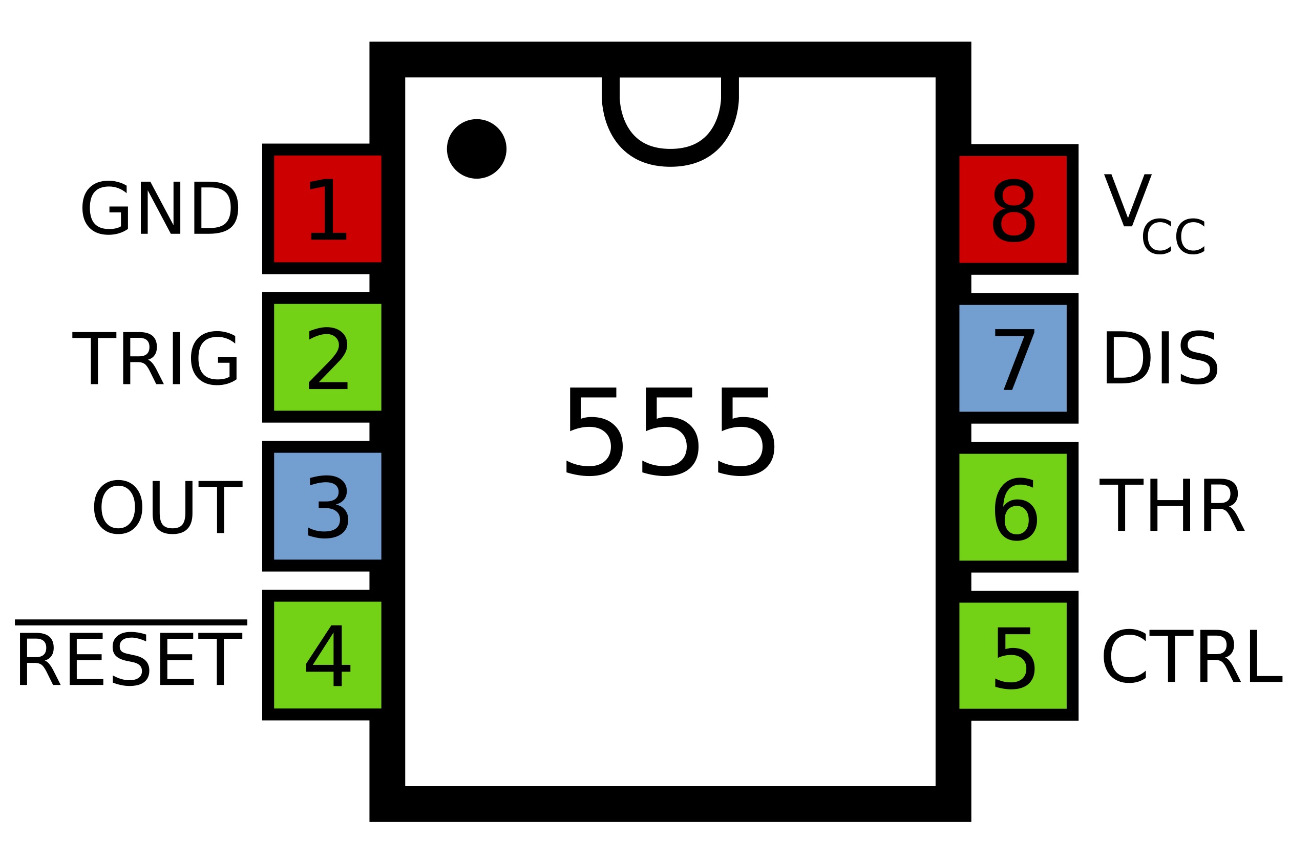
Before the 555 monostable circuit can be explained in detail, it is important to see what is actually inside the 555 timer!
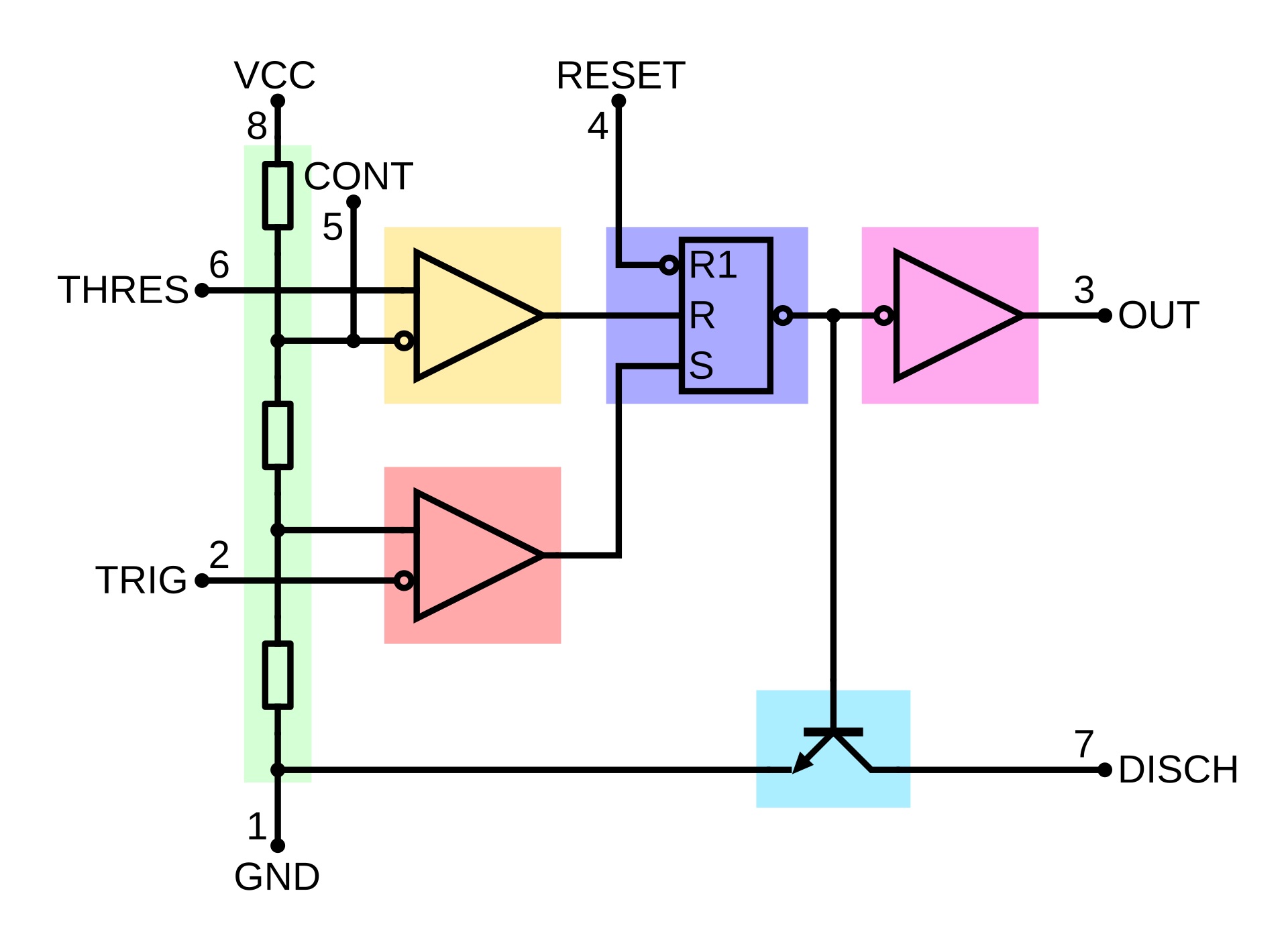
The image above shows the circuit diagram of what is inside a 555 timer IC. Looking at the internal circuit diagram of the 555 timer, the following can be seen:
✓ - 3 resistors (highlighted in green. 5kΩ each, hence the name 555)
✓ - A flip-flop (highlighted in blue. Has two resets)
✓ - Two comparators (one red (call this comparator 1), and one orange (comparator 2))
✓ - One inverter (highlighted in pink. Connects to the output)
✓ - One NPN transistor (highlighted in turquoise)
In the starting state of the circuit, the following is true
✓ - The voltage across the capacitor C1 is 0V
✓ - Both comparators inside the 555 chip have 0V on their outputs to the flip flop
✓ - The flip-flop is in reset mode
✓ - The flip-flop output voltage is therefore 9V
✓ - The 555 output voltage is 0V
✓ - The trigger input is at 9V (due to the pull-up resistor R1)
✓ - VCC is 9V
To start the monostable the trigger voltage needs to quickly be dropped to 0V. This is done by pressing the switch (when the switch contacts are shorted, the trigger input is connected directly to the ground and, therefore, will have a voltage of 0V). COMP1 inverting input is connected to the trigger pin, and the non-inverting input is connected to 1/3VCC. This means that normally the output of COMP1 is off but when the switch is pressed, the inverting pin (for a short time), is at a lower voltage than the non-inverting pin. Therefore the output of COMP1 is on for a short amount of time.
This short pules from COMP1 sets the flip flop and therefore, the output of the flip flop will be 0V. The flip-flop output is connected to the base of the discharge transistor, so when the switch is pressed, the transistor stops discharging the capacitor. Even when the switch is depressed, the transistor stays off because the flip flop remembers the last input (i.e., it stays latched). As the flip-flop output is 0V, the output stage of the 555 inverts this, and therefore, the output switches to 9V.
With the discharge pin no longer discharging, the capacitor C1 begins to charge through R3 and the potentiometer. Note that the capacitor is connected to the threshold input on the 555, which is internally connected to the non-inverting input to COMP2.
Eventually, the voltage across C1 will become larger than 2/3 VCC. Since the inverting input of COMP2 is connected to 2/3 VCC and the non-inverting input to the capacitor, the non-inverting input voltage will become greater than the inverting input. When this happens, COMP2’s output will turn on, which will, in turn, reset the flip-flop. This results in the flip-flop output being on and, therefore, turning on the discharge transistor. C1 very quickly discharges through the discharge transistor, making the voltage across C1 0V. Therefore, the output switches back to 0V, and the circuit is back in the starting state.
This circuit is called monostable because it is only stable in one state, the off state. While the 555 is in the on state, it will only be a matter of time (depending on the resistance of the potentiometer and the size of C1), before the system is reset back into the off state.
| Component | PCB Reference | Quantity | Looks Like |
|---|---|---|---|
| 8 DIP Socket | IC1 | 1 |  |
| 555 Timer IC | IC1 | 1 |  |
| 100nF Ceramic Disc Capacitor | C2 | 1 |  |
| 100uF Electrolytic Capacitor | C1 | 1 |  |
| 1K Resistor | R1, R2, R3 | 3 |  |
| 100K Linear Potentiometer | RV1 | 1 |  |
| 3mm Red LED | D1 | 1 | 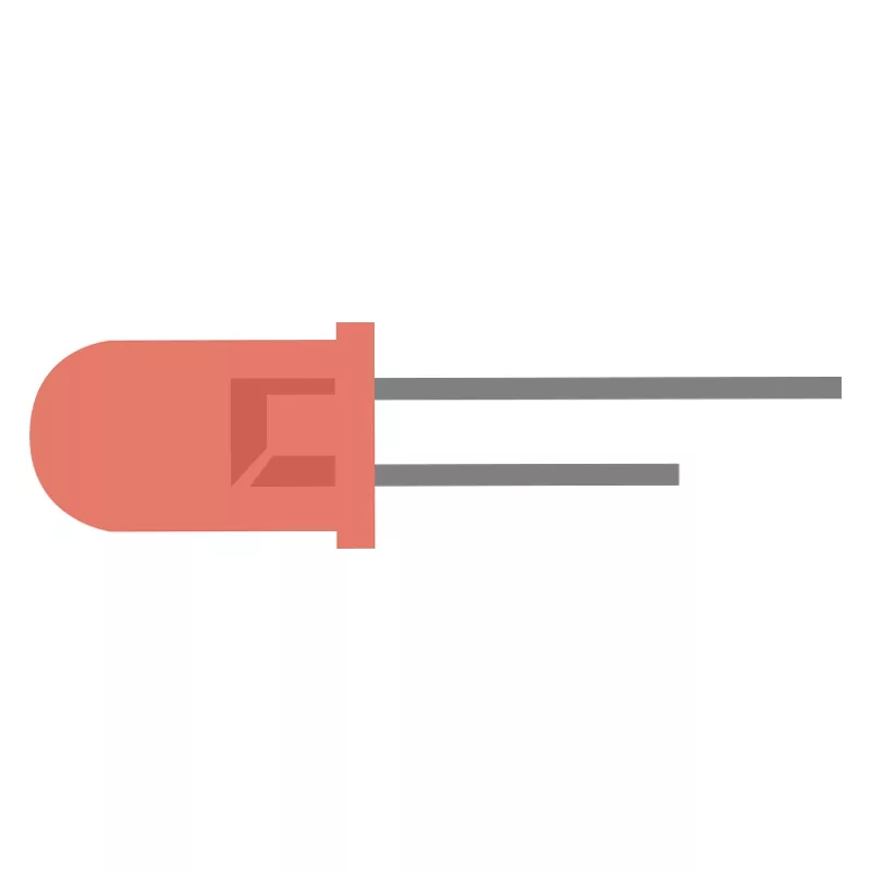 |
| Tactile Switch | SW1 | 1 | 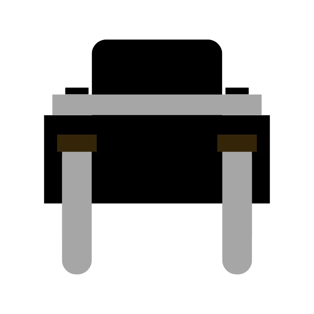 |
| PP3 Battery Connector | - | 1 | 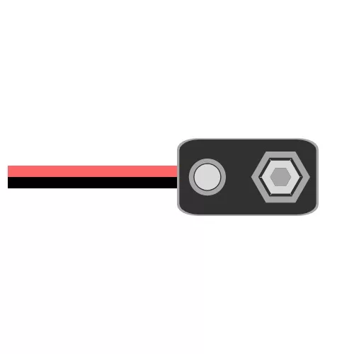 |
The 555 monostable circuit can be used to keep an output device on for an extended period after the button is pressed. For example, a button used to serve a drink could use a monostable to fill an entire glass by simply pressing a button once.
Another example of where a one-shot circuit could be used would be a door bell. One push of the button could be used to enable a buzzer for an extended period of time, and this removes the need to hold the button down.

Alarm circuits are useful for protecting valuable items and homes, but an alarm that goes off the moment the system is not only annoying but entirely impractical. As such, it is possible to use the 555 monostable circuit to provide a delay in the arming of an alarm. Pushing the button causes the 555 monostable to disable sensors for a brief moment of time which gives the user plenty of time to leave the area being protected.
A more advanced use for the 555 monostable is as a signal capturer. In cases where signals are too fast for a circuit to detect, a monostable can be used to produce a prolonged output upon detecting a rapid signal source. This is commonly used in applications that need to respond to fast-changing signals, and this is even used in the MitchElectronics Logic Probe to help detect short pulses.

To learn more about how to solder electronic components, download the Electronics Construction Manual free using the button below
Electronics Construction Manual
When soldering components, it is essential that you do so in a particular order, so that it is easy to add components and get to their legs. Generally, you always start with the smaller components (such as resistors and capacitors), before moving onto the larget parts (potentiometers and ICs).
Soldering Guide
Feeling brave? Consider using different resistors and capacitors
Can be done to build a 555 monostable with a different timing range

(+44) 7516 323 698

27 Willow Way, Meon Vale, CV37 8FT, United Kingdom

Co. House No. 14068499