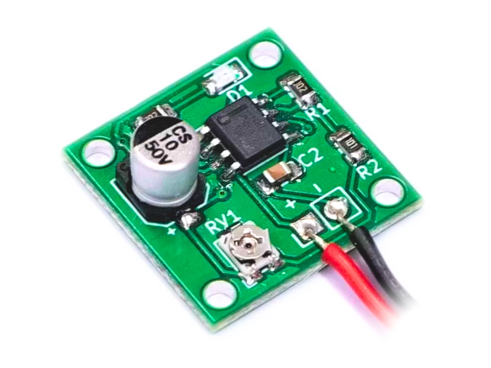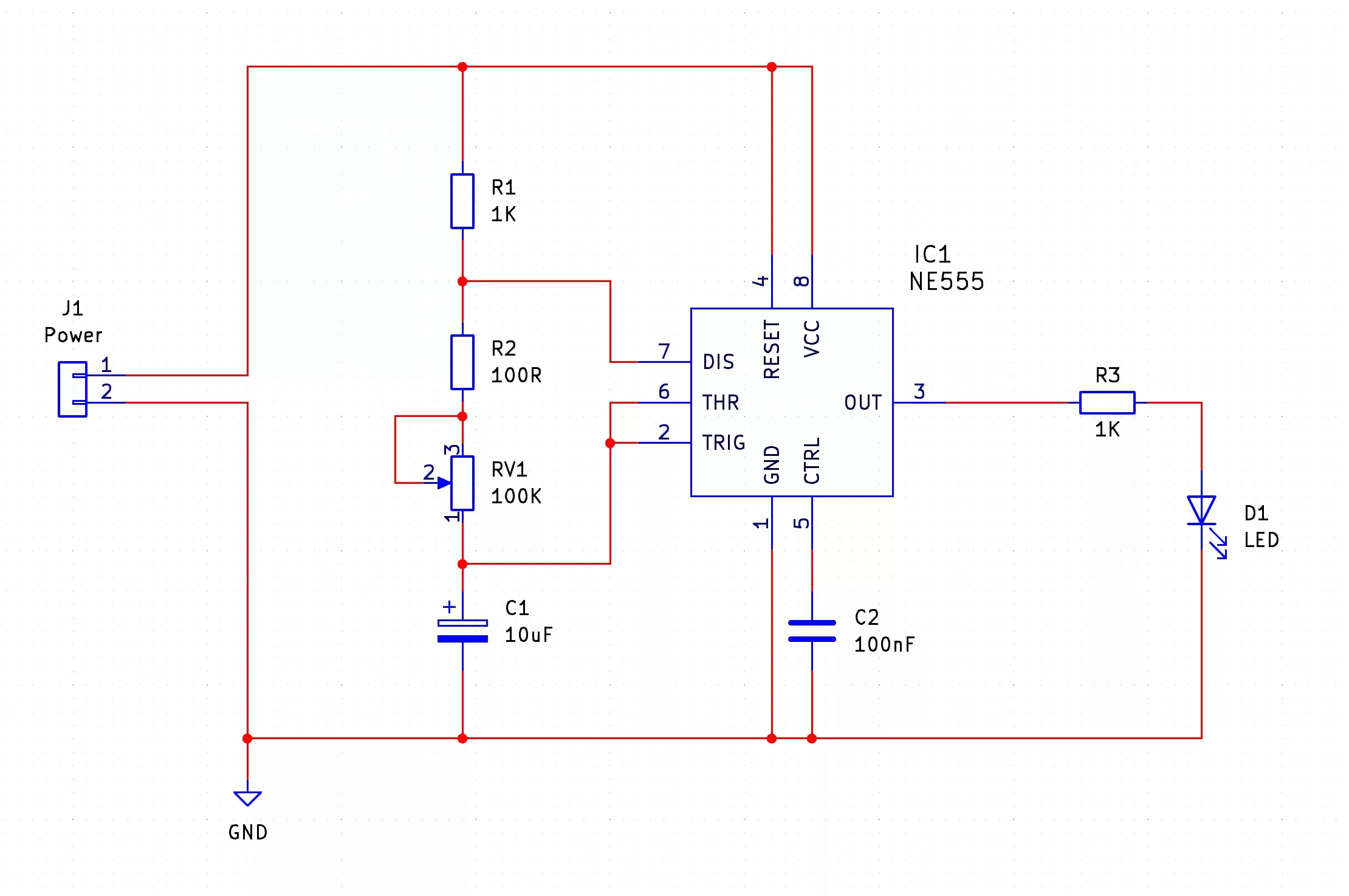
The 555 Astable SMD Trainer kit is designed to test your skills at SMD soldering and provides you with a small circuit that blinks. The frequency of the blink is determined by the value of the electrolytic capacitor and the setting of the potentiometer such that the smaller the size of the capacitor or resistance value of the potentiometer, the 555 astable will flash quicker. To learn more about the 555 timer and how it works, you can check out the instructions for the 555 Astable kit from MitchElectronics which also includes the internal circuit diagram of the 555 itself.
Besides the obvious use of improving your skills with soldering SMD parts, there are numerous uses for the kit. One potential application is to use the flashing LED as a night locator that can be attached to the back of a bag. Simply put, these kits can be ideal for quickly locating others at night during hikes in a similar fashion to tail and wing lights on planes.
On that note, the 555 Astable SMD Trainer can also be used on model RC planes that want to replicate the blinking lights used to locate craft at night. The SMD LEDs, albeit small, are brighter than you’d think, and can thus be used as a visual aid at a great distance during the night.
555 Astable circuits in general are also excellent for pulsing circuits that need to turn something on and off at regular intervals. One such example is a clock source for digital logic circuits that need a regular pulsing voltage (however, if using the 555 Astable with logic circuits, make sure the logic circuit operates at the same voltage as the 555 Astable otherwise you will likely damage the logic circuit).
| Component | PCB Reference | Quantity | Looks Like |
|---|---|---|---|
| 555 Timer IC SOIC8 | IC1 | 1 |  |
| 100nF 0805 Capacitor | C2 | 1 |  |
| 10uF Electrolytic Capacitor | C1 | 1 |  |
| 100R 0805 Resistor | R2 | 1 |  |
| 1K 0805 Resistor | R1, R3 | 2 |  |
| 100K SMD Potentiometer | RV1 | 1 |  |
| 0805 Red LED | D1 | 1 |  |
| PP3 Battery Connector | - | 1 |  |


To learn more about how to solder electronic components, download the Electronics Construction Manual free using the button below
Electronics Construction Manual
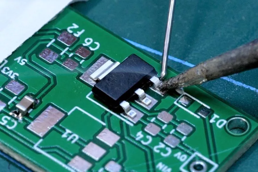
When soldering components, it is essential that you do so in a particular order, so that it is easy to add components and get to their legs. Generally, you always start with the smaller components (such as resistors and capacitors), before moving onto the larget parts (potentiometers and ICs).
Soldering Guide
To help keep the board stable when soldering, you can download a free STL model of a basic jig that can be 3D printed with all common 3D printers. Watch out for the mounting hole pins as they may be vulnerable to snapping if using a low infill density, low wall thickness, or thick layer heights. Additionally, do not use hot air to solder the PCB when using the jig as you will melt the jig.
Coming Soon...

(+44) 7516 323 698

27 Willow Way, Meon Vale, CV37 8FT, United Kingdom

Co. House No. 14068499