How to Identify SMD Components And Their Orientation
Table of Contents
Why Orientation Matters!
Not every component has its own unique appearance, and not all components can be put in any orientation (i.e., non-polarized). In fact, you will find that most SMD components, besides resistors and ceramic capacitors, must be oriented correctly, and worse, look like every other component. Because of this, it is absolutely essential that you not only recognise which components are polarised, but also be able to identify which way round they sit on the PCB as many SMD parts can easily be soldered incorrectly.
How To Identify SMD Parts
Resistors
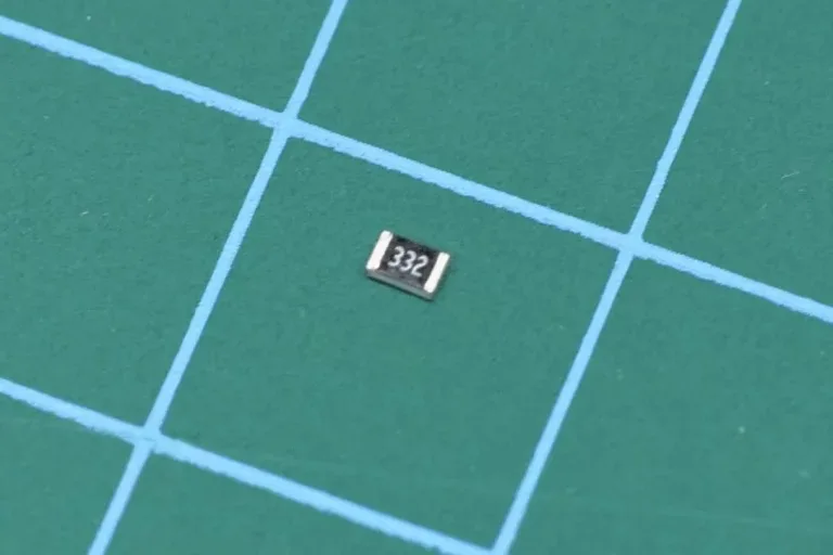
Resistors can be placed in any orientation as they are not polarised, and the resistors used in MitchElectronics kits use the 0805 package. On the top of the resistor is a three-number code that indicates its value, and just like capacitor codes, the first two numbers indicate the value, and the third number indicates the multiplier. For example, 103 would be 10 and then a multiplier of 1,000 which would give a value of 10KΩ.
SMD Resistor with the value 332 (3.3kΩ)
SMD Resistor Strip
If you find these numbers too small to read, it might be a good idea to use a multimeter to measure the resistance value, but remember that these resistors have a tolerance rating. Typically, the tolerance of carbon SMD 0805 resistor is ±5% meaning that the actual value will be within ±5% of the stated value. So, measuring 9.8kΩ would actually imply a 10kΩ resistor!
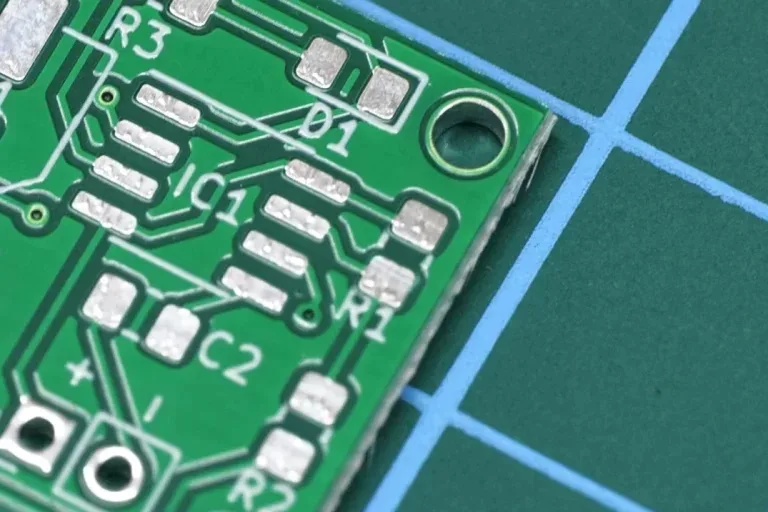
PCB pad showing resistor R1
Resistor correctly positioned before soldering
Ceramic Capacitors
Just like resistors, ceramic capacitors can be placed in any orientation as they are not polarised, but it is important to make sure that what you are soldering is indeed a ceramic capacitor. While resistors have numbers printed on them, ceramic capacitors almost never do, and this makes identification a nightmare. Luckily, MitchElectronics kits attach labels to each SMD strip, so it is important to ONLY TAKE OUT WHAT YOU NEED! If you start mixing capacitors together, you will struggle to identify them.
Ceramic SMD Capacitor
Cearmic Capacitor Strip
Also, capacitors come with tolerance values, but these are far larger than resistors with ±20% not being uncommon. Some multimeters give the option to measure capacitance, but not all, which is why having a multimeter with capacitance capabilities is a useful tool to have. So, if measuring the capacitance, keep in mind that the wide tolerance will show values very different to the stated capacitance.
Capacitor C2 PCB footprint
SMD capacitor positioned before soldering
Electrolytic Capacitors
Identifying the value of an electrolytic capacitor is also easy to do, and the first number on the top of the can almost always refer to the capacitance in microfarads (µF). For example, a code of 470 would correspond to 470µF, and a code of 10 would correspond to a 10µF.
Electrolytic SMD capacitor
The straight side on the left is the negative terminal
Electrolytic capacitors are polarised parts, and therefore must be placed on the PCB in a specific orientation. Thankfully, SMD electrolytic are very large SMD components, and identifying the correct orientation is very easy to do. The negative lead of the capacitor is indicated by a black strip on the top of the capacitor, and the corresponding negative lead on the PCB is identified by the straight edge. The positive lead on the PCB is typically indicated with either a plus symbol, a bent edge, or both. Soldering these parts is also very easy to do, and their large weight and size prevent tombstoning. As such, each lead is simply soldered in place using the standard soldering technique.
Capacitor C1 PCB footprint
Electrolytic capacitor positioned before soldering
LEDs
LEDs used in MitchElectronics kits use the 0805 packages, and this can make them a tad tricky to solder as they will be susceptible to tombstoning. But LEDs are also polarised components meaning that they only conduct in one specific direction, and this means that they must be correctly oriented on the PCB. On the LED itself, the cathode (i.e., negative pin) is typically designed with a very small stripe or arrow which points towards the cathode pin. This arrow may be on the underside of the LED, so you will need to pay special care to identify the cathode. If in doubt, you can use the diode testing function on a multimeter to confirm the polarization of the LED. On the PCB itself, the silkscreen of the LED also points to the cathode, but instead of being a pointy arrow, it is instead a squared U shape. The bottom of the U is where the cathode is.
SMD LED showing the small green cathode indicator
Underside of LED showing green arrow pointing to the cathode
Just as with any SMD 0805 component, you will need to watch out for tombstoning, and so holding down the LED with a pair of tweezers while touching one end of the LED will help to keep it in place.
SMD LED footprint D1 with cathode indicated by flat edge
The green indicator points towards the flat edge
SOT (Transistors & Linear Devices)
The term SOT stands for Small Outline Transistor, and these are commonly 3-pin devices used by transistors but are also used for regulators and special diode arrangements (such as bus protection). SOT parts come in many different shapes, styles, and sizes which is why no one soldering technique exists for them all.
With regards to orientation, it is impossible to place these components in the wrong way as they can only fit their outline in one specific direction. Three-pin devices typically have two pins on one side and one pin on the other, while four-pin devices typically have three pins on one side and a large tab on the other. SMD Voltage regulators (such as the AMS11117) used by MitchElectronics kits are always in larger SOT-223 outlines, and transistors will be in smaller SOT-23 packages.
SOT-223 is a common package for regulators
SOT-223 positioned before soldering
Soldering SOT-223 parts is straightforward, just position the component, solder a pin, check orientation and alignment, adjust as needed, and then solder the rest. However, do not solder the tab first as this can be tricky to reheat and adjust (always solder the tab last).
Soldering SOT-23 parts is not as easy as SOT-223 as they are incredibly small. While we could have chosen to use the larger SOT-223 package for transistors, we decided to make the SMD Trainer kits a tad more challenging, and thus went with the SOT-23. When soldering the SOT-23, it is best to solder the side with one pin first, check alignment, and then solder the remaining pads.
We use cookies to ensure that we give you the best experience on our website. If you continue to use this site we will assume that you are happy with it.OkNoPrivacy Policy