Soldering is a skill that takes time to get the hang of, but once you get it right, it’s hard to forget. There are countless hobbyists who haven’t picked up a soldering iron for a number of decades, only to find that the moment the iron is in their hand, it all comes back!
The soldering processes works as thus
Clean the PCB
Apply flux to the pads being soldered
Insert the component into the PCB and make sure it is oriented correctly
Solder the component by heating one side of the leg, and feeding solder to the other side
Remove the solder wire, followed by the iron
Inspect the quality of the joint and clean
How To Solder Video (In Under One Minute)
The Process, Step-By-Step
Step 1 - Clean The PCB
The cleaner your PCB, the better chance you have at producing professional solder joints. All PCBs that MitchElectronics produces have strict quality controls to make sure that all PCBs are protected against corrosion and containments, but upon opening the kit, a quick wipe down with some electronics-grade alcohol can be helpful. Electronics grade alcohol is typically greater than 90% IPA, and the higher you can get, the better!
Make sure your PCB is clean, otherwise solder may not stick!
Step 2 - Apply Flux
Of all the steps you can do, this by far is one of the most important. Flux is a chemical that, when heated, breaks down into an acid and eats away at oxides and oils leaving behind the ultimate soldering surface. Flux can come in numerous forms including liquid dispensers that can be brushed onto the PCB, in liquid pens that can be drawn on, and even as a paste (but paste is often used by plumbers and not electronic engineers). Of all the flux options available, we strongly suggest the pen variety as they are small, cheap, and convenient to use.
However, there is a dark side to flux; it is corrosive over time. While this is unlikely to happen to MitchElectronics kits due to their simplicity, flux left on PCBs can see track and solder mask destruction over a number of years. That is why commercial electronics are often cleaned after soldering to remove as much flux as possible (cleaning is typically done in an ultrasonic bath with anti-flux chemicals).
Flux will eat at oxides and improve soldering massively
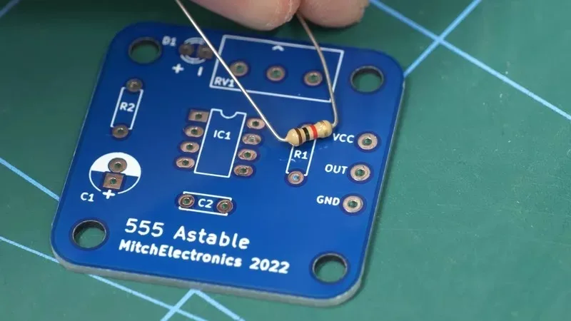
Step 3 - Insert Components Into PCB
With the PCB cleaned and flux applied, the next step will be to insert the component to be soldered. It is essential that the component is checked for both its type, value, and reference as once a part is soldered to a PCB, removing it can be extremely challenging (not impossible). On all MitchElectronics kits, only component references are printed on the PCB, meaning you will need to check the schematic for that kit against the part you are inserting.
Some components, such as ceramic capacitors and resistors, are no polarised meaning they can be inserted in any orientation, but others, such as electrolytic capacitors, transistors, and integrated circuits, can only be inserted in one specific orientation for them to work correctly. To learn more about identifying components and their orientation, look at our electronics construction guide.
Confirm the part matches the reference
It can be helpful to bend the legs to keep in place
Step 4 - Solder The Component Leg
Arguably the most important step, soldering a component leg needs to be done quickly but carefully. The biggest mistake that newcomers to electronics make is that they try to put solder onto the iron tip, and then wipe this solder onto the leg being soldered. That is NOT how to solder, as the solder will quickly oxidise and refuse to wet correctly.
To solder a component leg, start by touching both the pad and one side of the leg being soldered; this will begin to heat up the leg and pad. After a second or two, bring your solder wire to the opposite side of the pad and leg being heated, making contact with the pad and leg. If done correctly, solder wire should immediately melt and be sucked up towards the soldering iron tip.
Heat one side with the iron first...
... then feed the solder wire in
Step 5 - Remove Solder Wire
With a nice joint now having been formed, the solder wire needs to be removed before the soldering iron tip is removed. If the iron tip is removed first, the joint can quickly solidify and stick to the solder wire reel. The entirety of steps 4 and 5 should be done in a matter of seconds, otherwise, components are at risk of being damaged by the extreme heat. Thus, steps 4 and 5 should apply tip, melt wire, remove wire, and remove the tip, all faster than saying “MitchElectronics is the best place for kits”.
Remove the wire while still heating the joint
Solder joint complete
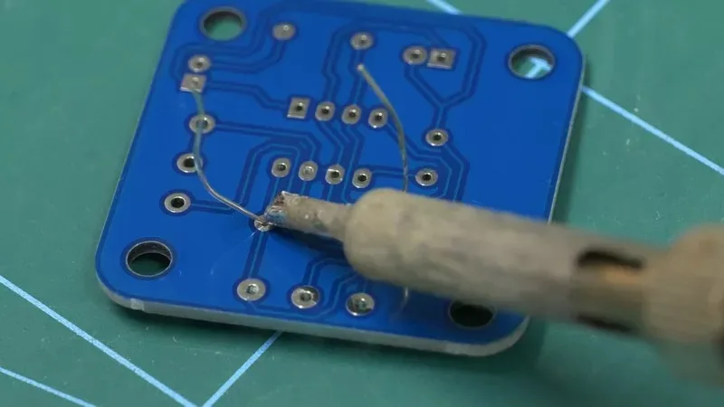
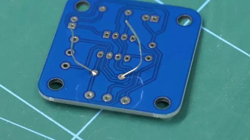
Step 6 - Inspect & Clean
At this point, the joint should be inspected to see if it has the characteristic volcano shape, free from roughness, and is shiny. The volcano shape is ideal as this indicates the perfect balance between solder quantity and surface quality. A poor quality joint with impurities and oxidation will struggle to form the volcano shape, which arises from surface tension. With lead-free solder, you may find that your solder joints are volcano shaped and smooth, but not shiny. So long as the solder joint is volcanic, it is most likely that the joint has worked well.
Closeup of volcanic shape
A perfect solder job
Finally, the joint needs to be cleaned of any and all remaining flux as flux, if left, corrodes the PCB. At the end of the day, flux is an acid, and leaving flux can lead to damage over a long period of time (it takes years for flux to damage a PCB). Cleaning a PCB should be done with IPA as this will dissolve flux while leaving alone everything else. A cotton bud soaked in IPA does a good job with component pads and legs.
Tin snips can be handy at cutting excess component legs
We use cookies to ensure that we give you the best experience on our website. If you continue to use this site we will assume that you are happy with it.OkNoPrivacy Policy