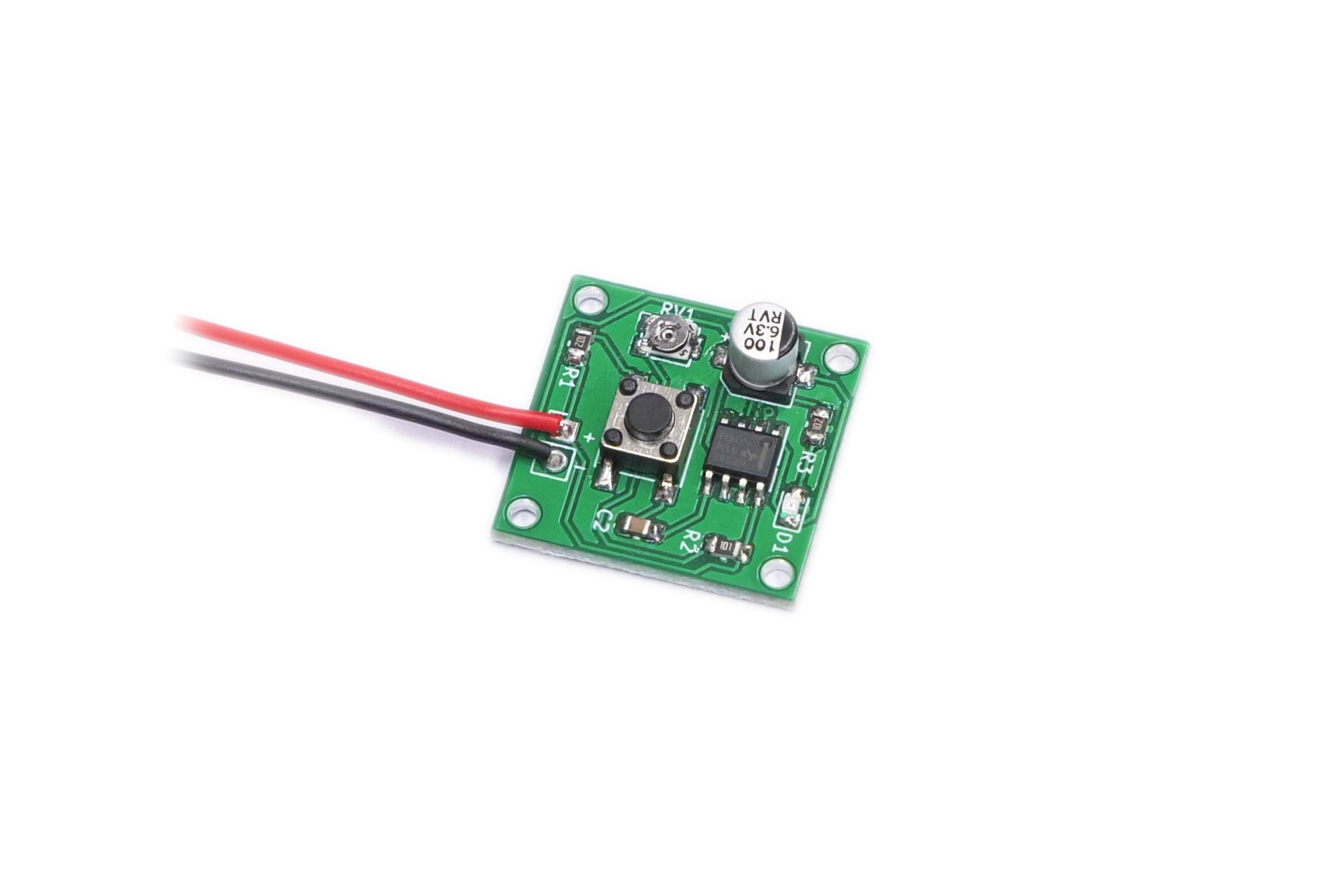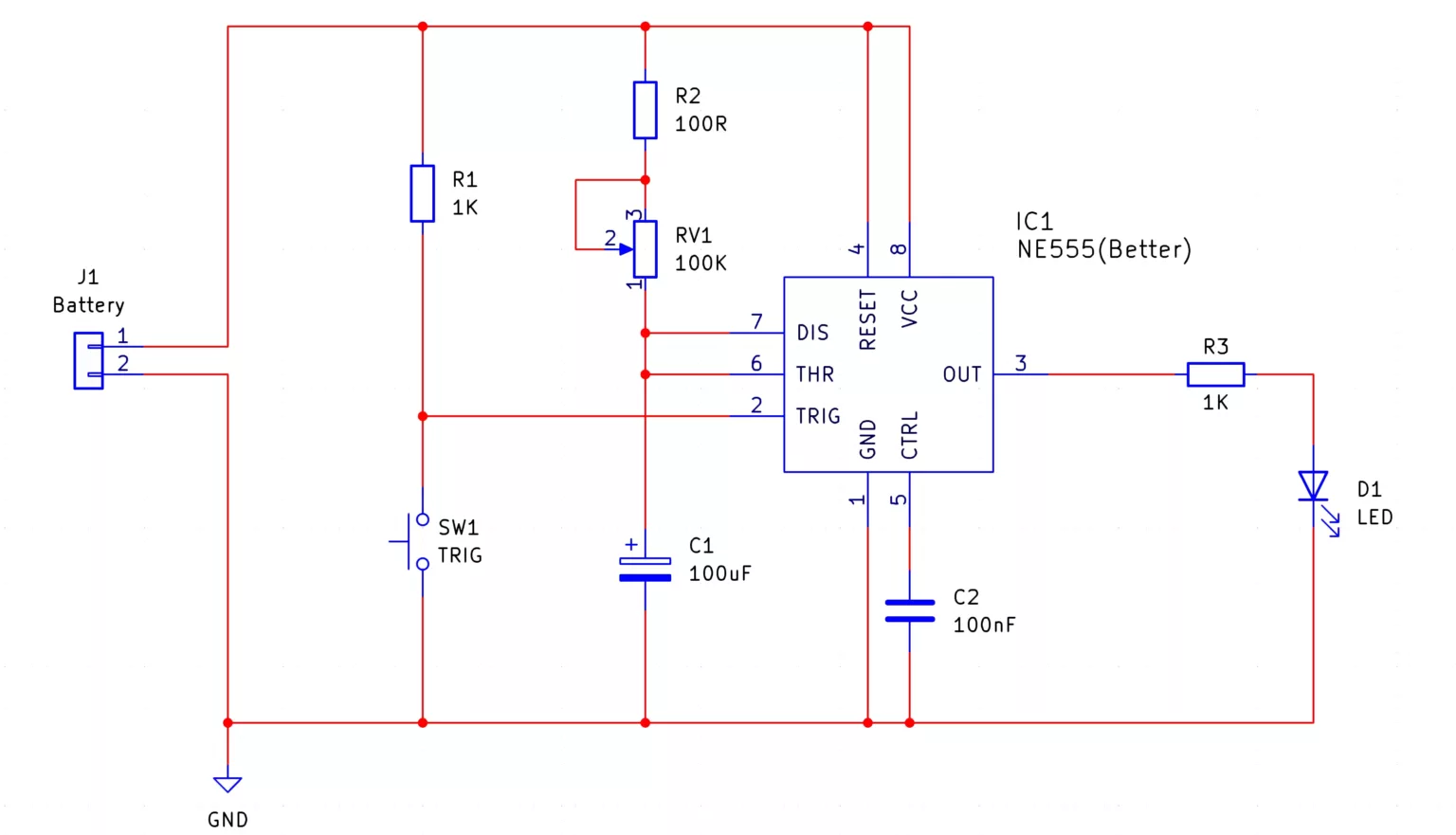
The 555 Monostable SMD Trainer kit is designed to test your skills at SMD soldering and provides you with a small circuit that blinks for a period of time once pushing the button. The length of time the LED remains on is determined by the value of the electrolytic capacitor and the setting of the potentiometer such that the smaller the size of the capacitor or resistance value of the potentiometer, the period will be smaller. To learn more about the 555 timer and how it works, you can check out the instructions for the 555 Monostable kit from MitchElectronics which also includes the internal circuit diagram of the 555 itself.
Besides the obvious use of improving your skills with soldering SMD parts, there are numerous uses for the kit. One potential use for the monostable is to act as a bolt lock mechanism for a door such that entering the correct code causes a bolt to briefly retract. If the door isn’t opened within a set time delay, the monostable re-engages the lock to prevent it from being left open.
Another use for the 555 Monostable is to control the spout of an automated drinks dispense. A small DC pump connected to a motor driver and 555 monostable can be configured to deliver exact amounts of fluid, and these can include water, juice, and fizzy drinks.
Finally, the 555 monostable can also be used to control a power relay that enables a mains device to operate for a specific amount of time before automatically turning it off. For example, a games console can be connected to a monostable controller which prevents kids from playing for too long, and another example would be a sprinkler system that only remains on for a set period of time once activated.
| Component | PCB Reference | Quantity | Looks Like |
|---|---|---|---|
| 555 Timer IC SOIC8 | IC1 | 1 |  |
| 100nF 0805 Capacitor | C2 | 1 |  |
| 100uF Electrolytic Capacitor | C1 | 1 |  |
| 100R 0805 Resistor | R2 | 1 |  |
| 1K 0805 Resistor | R1, R3 | 2 |  |
| 100K SMD Potentiometer | RV1 | 1 |  |
| SMD Tactile Switch | SW1 | 1 |  |
| 0805 Red LED | D1 | 1 |  |
| PP3 Battery Connector | - | 1 |  |


To learn more about how to solder electronic components, download the Electronics Construction Manual free using the button below
Electronics Construction Manual
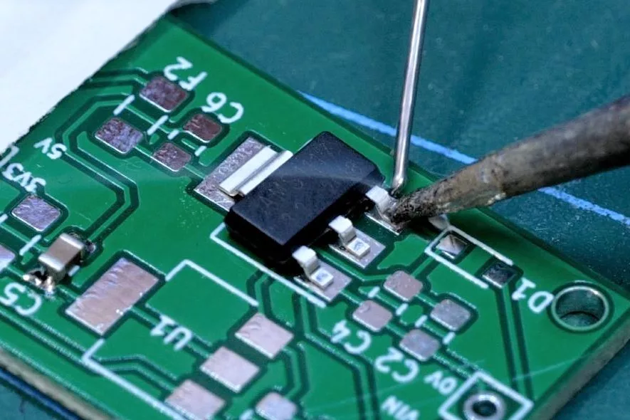
When soldering components, it is essential that you do so in a particular order, so that it is easy to add components and get to their legs. Generally, you always start with the smaller components (such as resistors and capacitors), before moving onto the larget parts (potentiometers and ICs).
Soldering Guide
To help keep the board stable when soldering, you can download a free STL model of a basic jig that can be 3D printed with all common 3D printers. Watch out for the mounting hole pins as they may be vulnerable to snapping if using a low infill density, low wall thickness, or thick layer heights. Additionally, do not use hot air to solder the PCB when using the jig as you will melt the jig.

(+44) 7516 323 698

27 Willow Way, Meon Vale, CV37 8FT, United Kingdom

Co. House No. 14068499