Breadboards are a solder-less technology meaning that breadboards require no soldering irons. This makes them ideal for those looking to reuse components as well as those who want to reduce the risk from harm dealing with molten solder. At the same time, breadboards are also extremely quick to use, making them excellent for rapid prototyping.
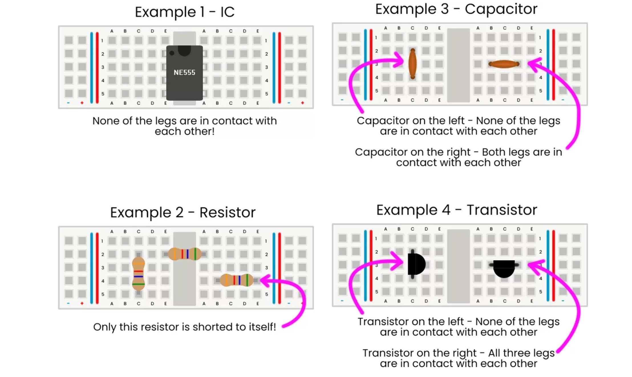
However, as breadboards rely on components being pushed into holes with weak grips, breadboards are not ideal for applications that require reliability. For example, a breadboard circuit placed near strong vibrations, forces, or drops, will quickly fall apart. At the same time, breadboards use holes with a pin pitch of 2.54mm, meaning that they only work with through-hole parts, and components that have pin pitches of 2.54mm. Furthermore, the structure of breadboards, as we will see shortly, means that only parts with single or dual-line designs will fit on a breadboard.
Breadboards come in all kinds of shapes and sizes, but generally speaking, all have one design feature in common; two sides of contacts that form rows.
Breadboards are made up of columns and rows, with rows being electrically connected (i.e., continuity), and columns being isolated. Down the centre of a breadboard is a dividing line that splits rows into two halves, with each half being electrically isolated from each other. Sometimes, the edges of breadboards can have power rails which connect along the entire column, making it easier to connect power supplies to circuits on the breadboard.
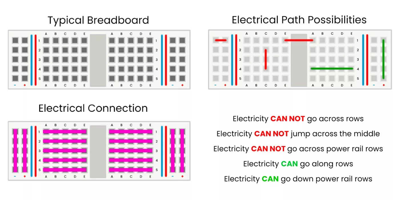
Inside each row is a single metal spring contact that spans the entire length of the row. When a component leg is pushed into a hole, the contact is opened up, and the springy nature of the contact grips the part in place. Any other components who are inserted into the same row will all be electrically connected to each other.
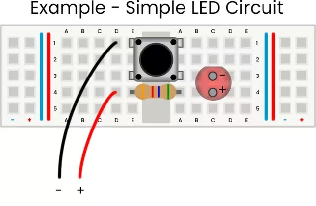
This circuit demonstrates the simplest circuit of all, the humble light and switch. The purpose of this example is to demonstrate how electricity flows through a breadboard circuit.
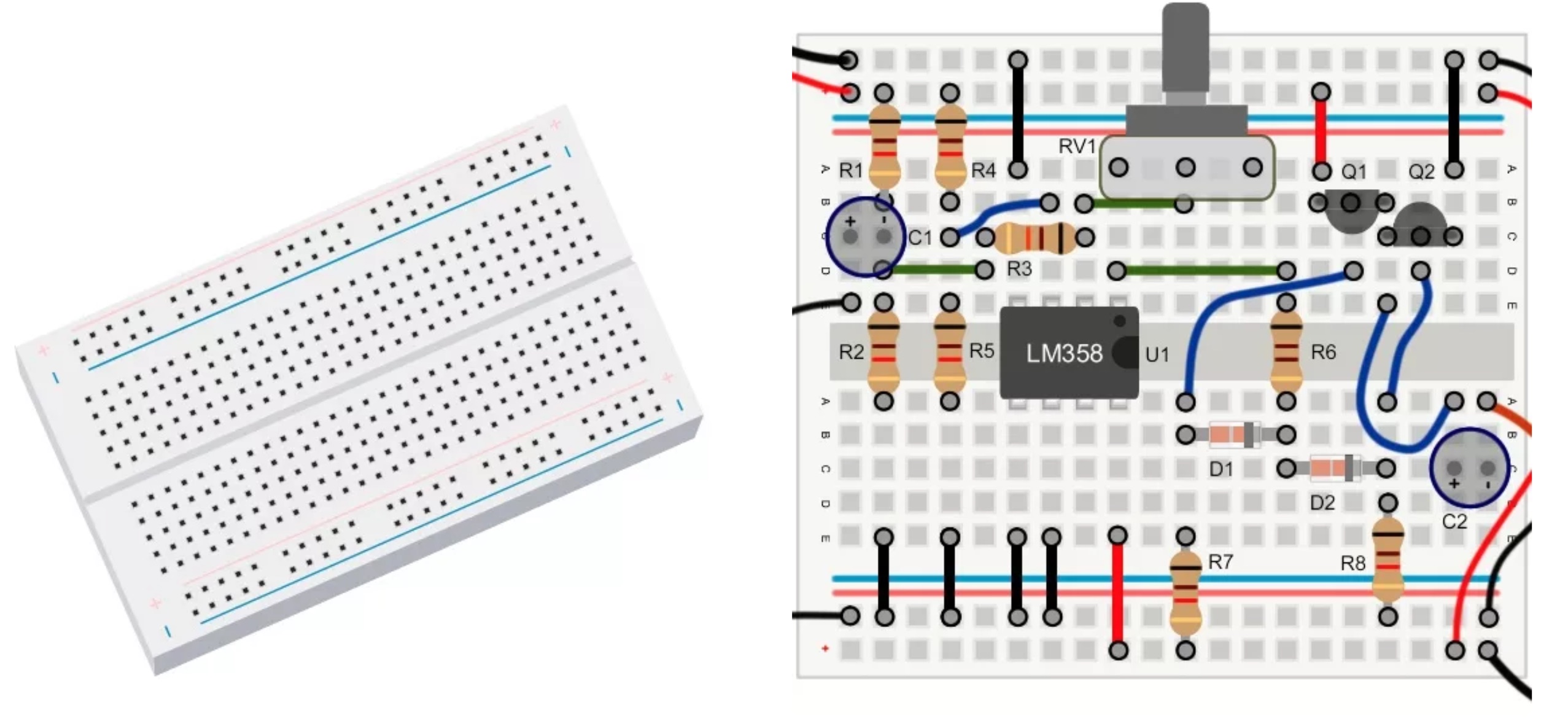
The transistor flasher is a circuit that consists of two transistors and flashes two LEDs one after the other. The exact explanation of how this works is too complicated to explain here but can be found in the MitchElectronics transistor flasher kit (see link here).
However, the simple explanation is that each transistor is controlled by a capacitor whose charging/discharging is controlled by the other transistor. The effect of this circuit is that each transistor takes, in turn, to turn on and off, and this circuit is known as an astable circuit as the circuit is not stable in either state. The breadboard layout for the transistor flasher is shown below.

(+44) 7516 323 698

27 Willow Way, Meon Vale, CV37 8FT, United Kingdom

Co. House No. 14068499


