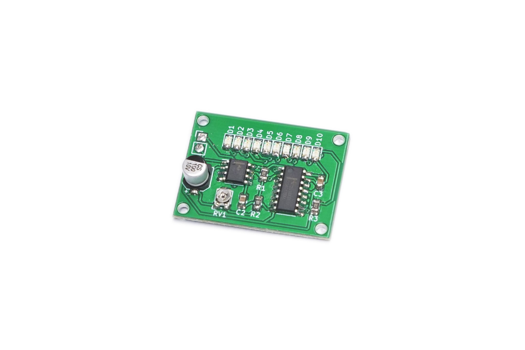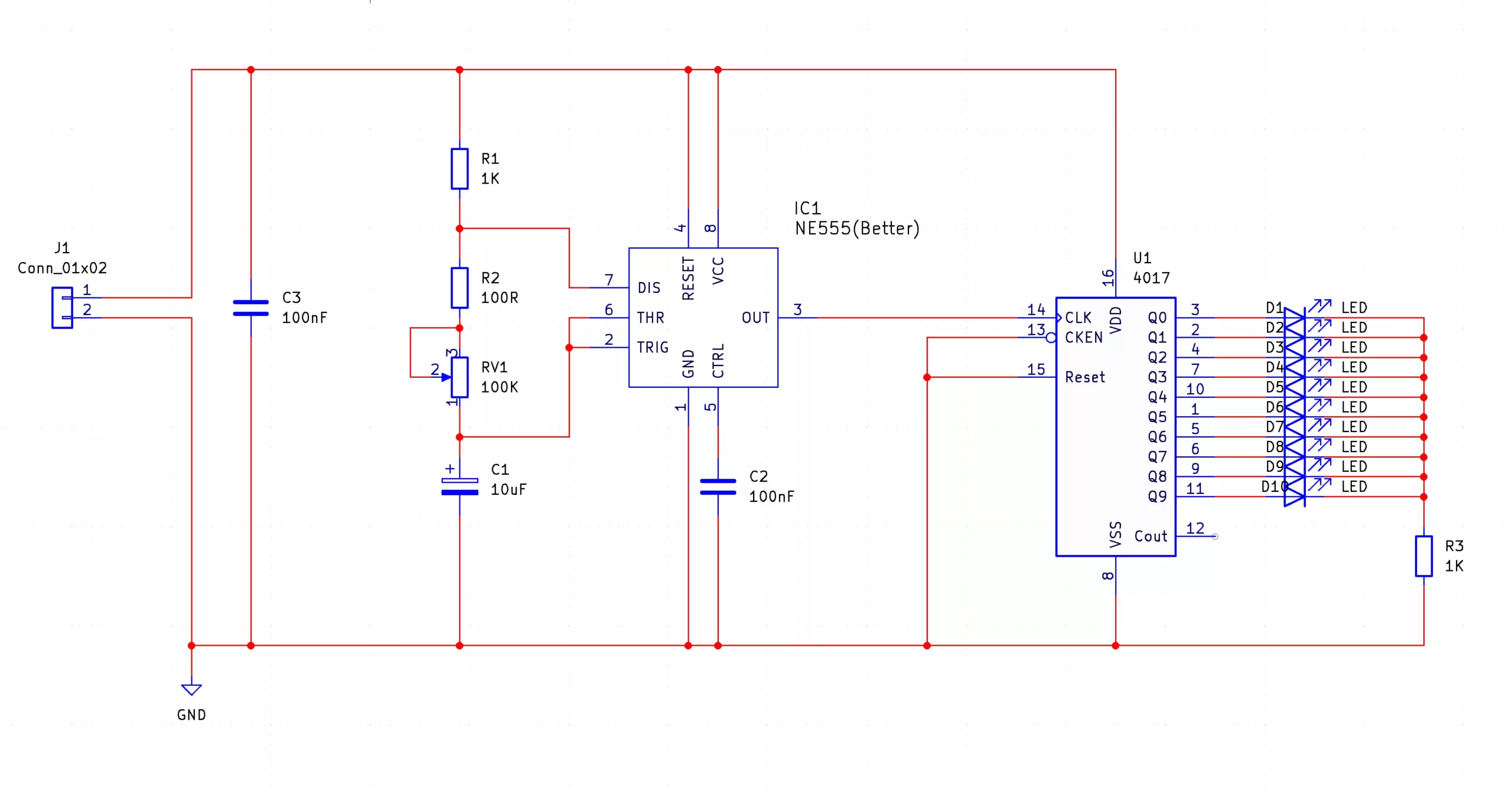
The 4017 light chaser SMD Trainer kit will let you build the famous 4017 light chaser circuit using only SMD parts. Unlike the 555 Astable and Monostable, the 4017 Light Chaser kit integrates both a 555 (as a clock source), and a 4017 Johnson counter that is used to sequentially light up LEDs. The frequency of the 555 astable determines the speed at which the 4017 counts, and the frequency of the 555 astable is determined by the value of the potentiometer RV1 and capacitor (a smaller RV1 and/or C1 results in a faster count). As the aim of this kit is to introduce you to SMD soldering, the theory behind the circuit will not be covered here, but instead can be learned from the MitchElectronics 4017 Light Chaser kit.
Besides the obvious use of SMD training, the 4017 light chaser can be used in many different projects. One such popular example is cosplay which requires a constant stream of LED light that supposedly moves around the costume. The 4017 Light Chaser is also good for sequential control if used with other circuits with each LED being replaced with a logic circuit.
Another fantastic use of the 4017 light chasers is model RC runways and dioramas. If the LEDs are replaced with cables that go to individual LEDs, it is possible to create a runway whose LED pattern blinks in the direction of plane landings. Finally, the 4017 Light Chaser is one of those projects that is neat to build, and can be a cool gizmo to have blinking away on the desk.
| Component | PCB Reference | Quantity | Looks Like |
|---|---|---|---|
| 555 Timer IC SOIC8 | IC1 | 1 |  |
| 4017 Counter IC SOIC16 | U1 | 1 |  |
| 100nF 0805 Capacitor | C2, C3 | 2 |  |
| 10uF Electrolytic Capacitor | C1 | 1 |  |
| 100R 0805 Resistor | R2 | 1 |  |
| 1K 0805 Resistor | R1, R3 | 2 |  |
| 100K SMD Potentiometer | RV1 | 1 |  |
| 0805 Red LED | D1 - D10 | 10 |  |
| PP3 Battery Connector | - | 1 |  |


To learn more about how to solder electronic components, download the Electronics Construction Manual free using the button below
Electronics Construction Manual
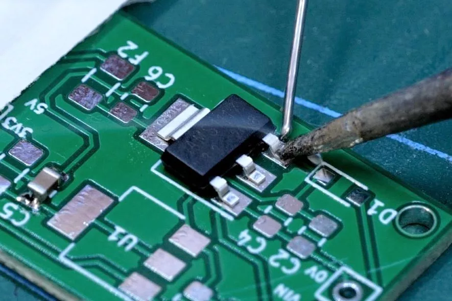
When soldering components, it is essential that you do so in a particular order, so that it is easy to add components and get to their legs. Generally, you always start with the smaller components (such as resistors and capacitors), before moving onto the larget parts (potentiometers and ICs).
Soldering Guide
To help keep the board stable when soldering, you can download a free STL model of a basic jig that can be 3D printed with all common 3D printers. Watch out for the mounting hole pins as they may be vulnerable to snapping if using a low infill density, low wall thickness, or thick layer heights. Additionally, do not use hot air to solder the PCB when using the jig as you will melt the jig.

(+44) 7516 323 698

27 Willow Way, Meon Vale, CV37 8FT, United Kingdom

Co. House No. 14068499