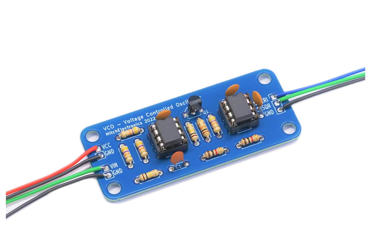
The Voltage Controlled Oscillator (VCO for short), is a very practical circuit for generating square and sine waves. While these waves can be produced using the Simple Function Generator Kit, the VCO allows for controlling the output frequency with the use of a voltage signal instead of using a potentiometer. This means that the output frequency of the VCO can easily be controlled by microcontrollers and other analogue circuits which can create some pretty interesting results. For example, a 1V octave synthesiser can be built using this module whereby a 1V octave keyboard is connected to an exponential converter which feeds its output into the VCO to produce keyboard tones. This circuit can also be used in retro ways such as sensor data transmission where the voltage output of a sensor is converted into a frequency and the frequency of the output will be proportional to the sensor reading (a similar system was done in early satellites such as Sputnik).
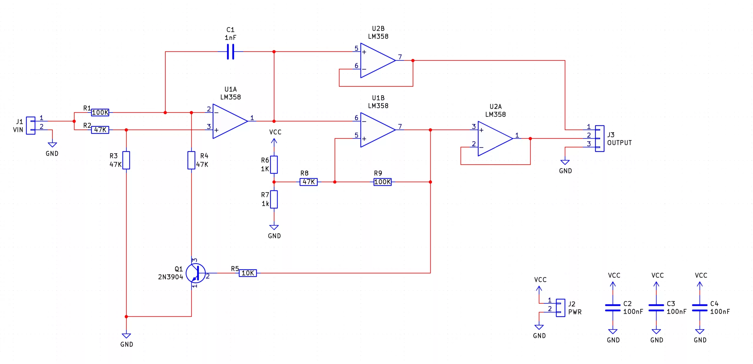
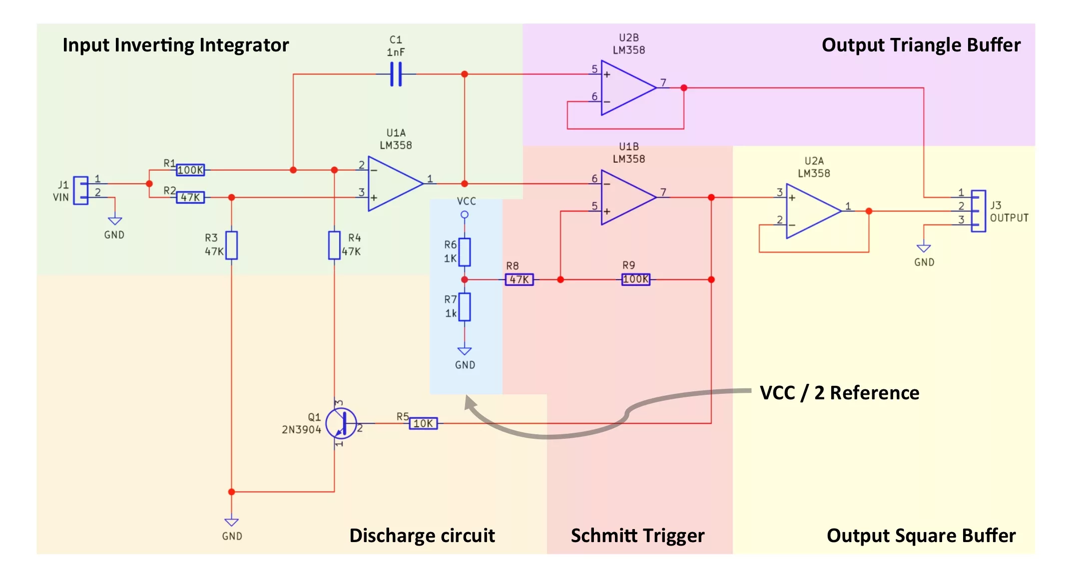
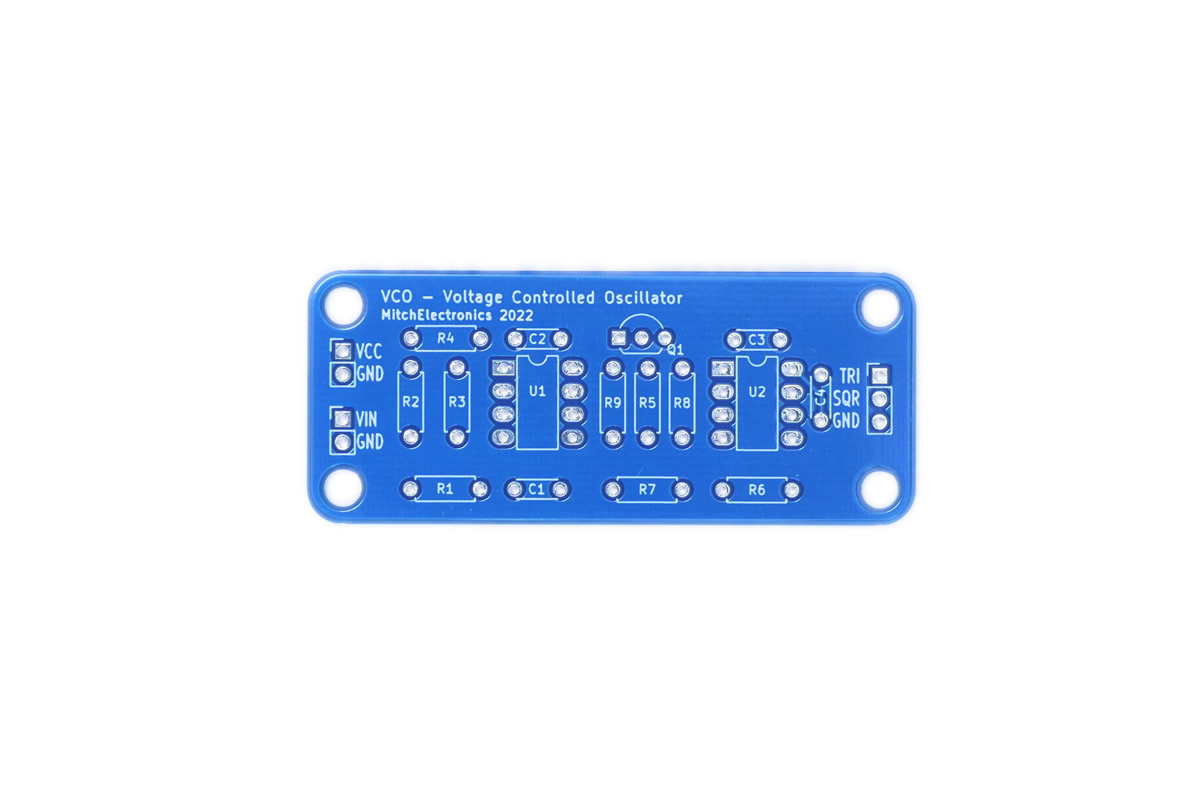
The VCO is a complex circuit and so only an overview of its workings will be presented in this instruction manual. The VCO consists of the following sub-circuits (refer to the blocktised schematic to see these sub-circuits):
- Integrator Circuit
- Schmitt Trigger Circuit
- Voltage Reference
- Discharge Circuit
- Output Buffers
The input to the VCO is fed into the integrator circuit and the purpose of the integrator circuit is to produce each side of the triangular waveform (steadily increasing or steadily decreasing). The larger the input to the integrator the faster the voltage rises/falls and the smaller the input voltage the slower the voltage rises/falls. The integrator feeds its output into an inverting Schmitt trigger whose hysteresis points are determined by resistors R8 and R9. If the output of the integrator goes beyond the upper hysteresis limit then the output of the inverting Schmitt trigger turns off. If the output of the integrator goes lower than the low- er hysteresis limit then the output of the inverting Schmitt trigger turns on.
The output of the inverting Schmitt trigger is also connected to a discharge transistor Q1 which controls whether the output of the integrator should rise or fall. If the output of the inverting Schmitt trigger is high then the discharge transistor is turned on and therefore the output of the integrator begins to rise (as it's an inverting integrator). If the output of the inverting Schmitt trigger is low then the discharge transistor is turned off and therefore the output of the integrator begins to fall.
So to sum up how the system oscillates:
- Integrator output begins to rise and eventually crosses the upper threshold of the Schmitt trigger
- The Schmitt triggers output switches off and this turns off the discharge transistor
- The integrators output begins to fall and eventually crosses the lower threshold of the Schmitt trigger
- The Schmitt triggers output switches on and this turns on the discharge transistor
- The discharging transistor causes the output of the integrator to rise and we go back to step 1
The two buffers are used to provide signal outputs that do not affect the VCO oscillation. The square wave output is obtained from the Schmitt triggers output as this switches on and off while the triangular waveform is obtained from the integrator output (as this steadily rises and falls). The triangular waveform has a DC offset and this can be removed with the use of a coupling capacitor. The process cycle of the VCO is shown below.

| Component | PCB Reference | Quantity | Looks Like |
|---|---|---|---|
| 8 DIP Socket | U1, U2 | 2 |  |
| LM358 Dual Op-Amp IC | U1, U2 | 2 |  |
| 1K Resistor | R6, R7 | 2 |  |
| 10K Resistor | R5 | 1 | 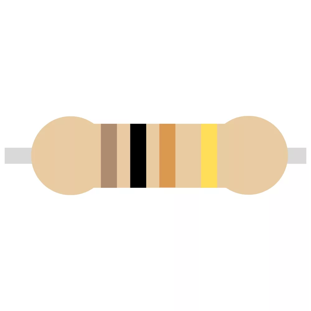 |
| 47K Resistor | R2, R3, R4, R8 | 4 | 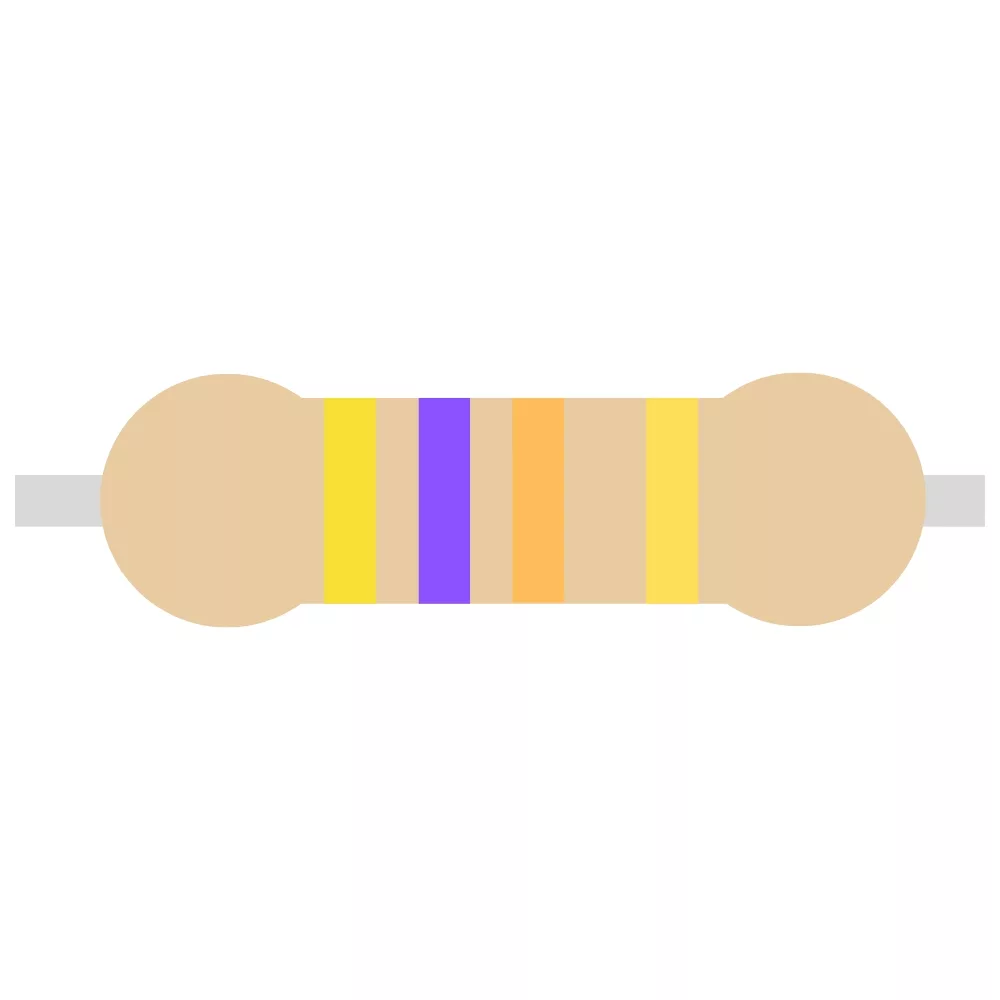 |
| 100K Resistor | R1, R9 | 2 | 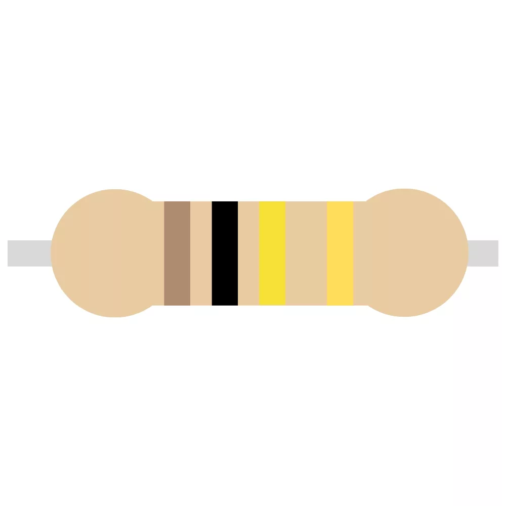 |
| 1nF Ceramic Disc Capacitor | C1 | 1 | 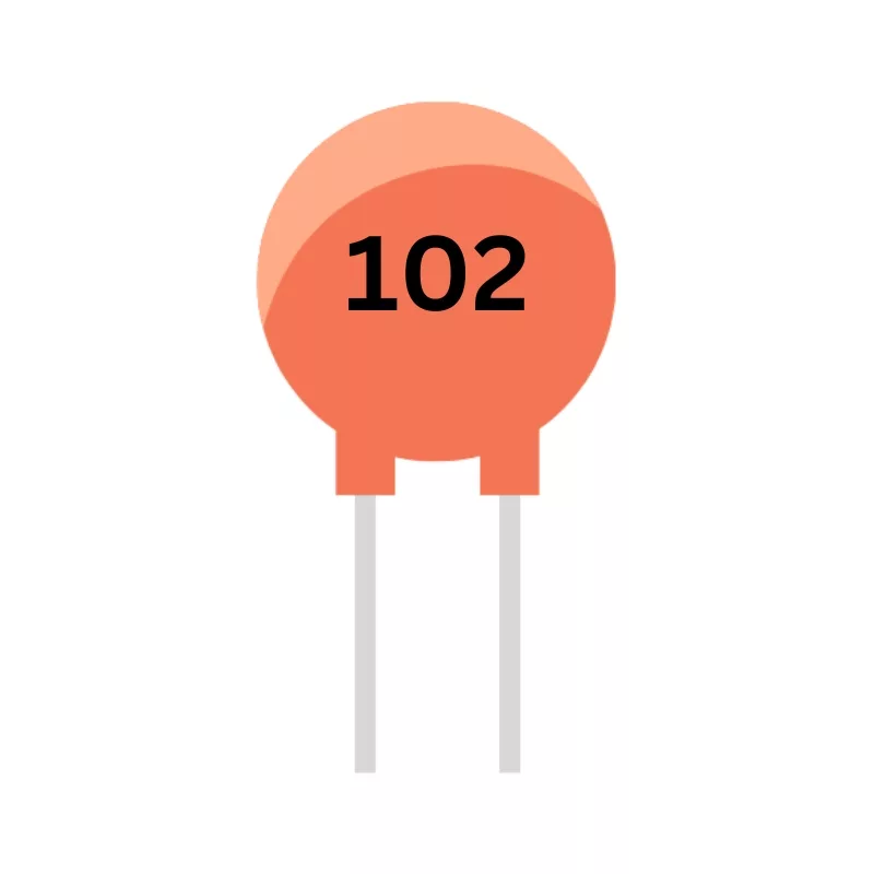 |
| 100nF Ceramic Disc Capacitor | C2, C3, C4 | 3 |  |
| 2N3904 NPN Transistor | Q1 | 1 |  |
| Red Wire | VCC | 1 |  |
| Blue Wire | VIN, TRI | 2 |  |
| Green Wire | SQUARE | 1 |  |
| Black Wire | GND | 2 |  |
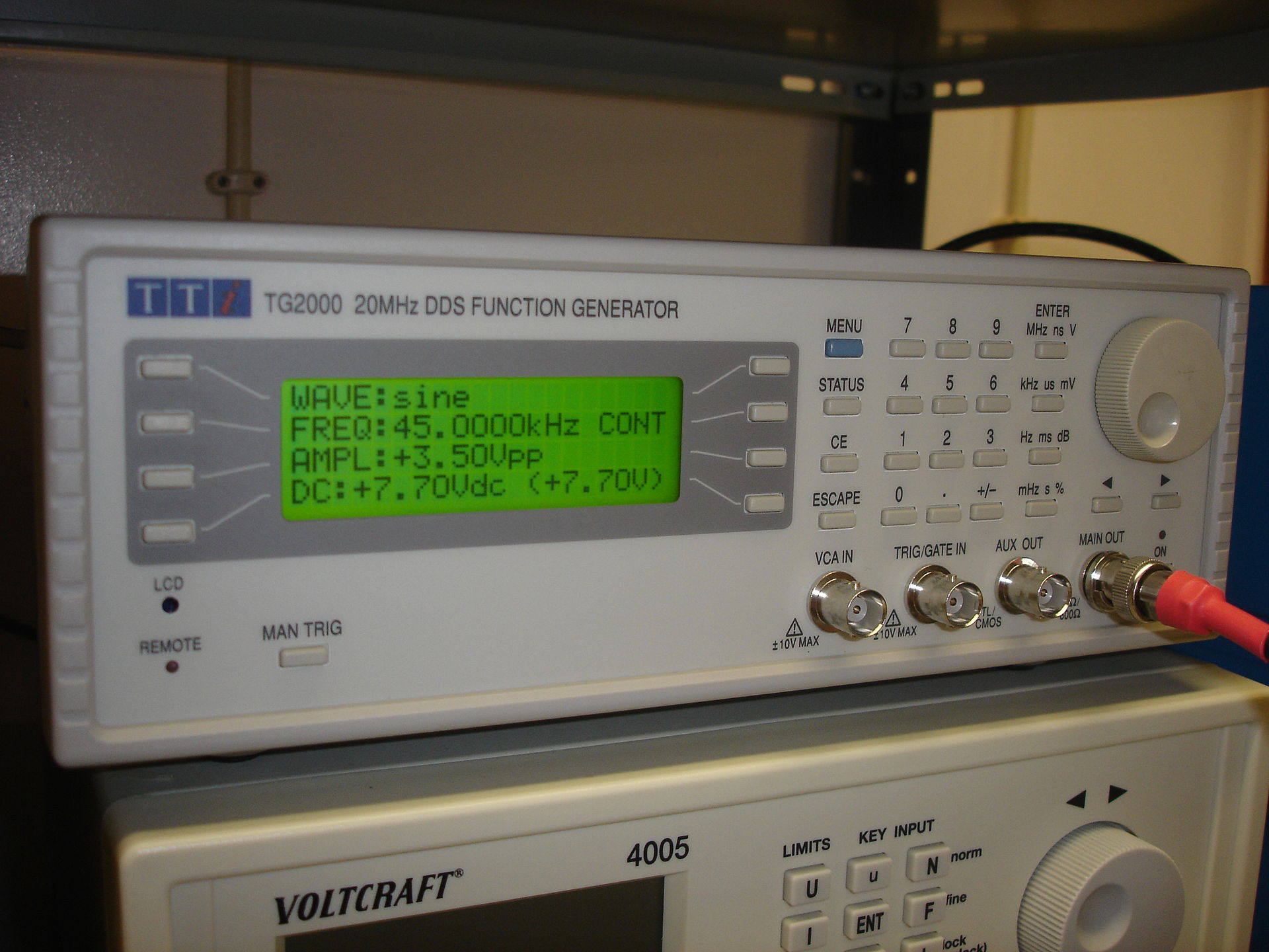
Function generators are extremely expensive pieces of equipment that will likely contain many features you don’t need. As such, the Voltage Controlled Oscillator Kit provides an excellent alternative that is not only much cheaper but easier to use and interface with. If you require more complexity, you can add extra circuits to the output of each waveform, and enclosing the Voltage Controlled Oscillator in a case can make a very neat and practical project!
The Voltage Controlled Oscillator produces both square and triangle waves which are both highly popular with old consoles. As such, the Voltage Controlled Oscillator kit can be used as a synthesiser either on its own, or combined with external analogue voltages. Furthermore, both the square and triangular waves can be mixed together to create some really unusual sounds!
Did you know that if you pass a triangular wave through several low-pass filters you can create a sine wave? As such, a sine wave source can be made from the Voltage Controlled Oscillator, and this can be used for creating inverters, modulation systems, and so much more!

To learn more about how to solder electronic components, download the Electronics Construction Manual free using the button below
Electronics Construction Manual
When soldering components, it is essential that you do so in a particular order, so that it is easy to add components and get to their legs. Generally, you always start with the smaller components (such as resistors and capacitors), before moving onto the larget parts (potentiometers and ICs).
Soldering Guide
Change the value of the capacitors and resistors to adjust the frequency of oscillation
Connect multiple VCOs together to create complex synthesisers

(+44) 7516 323 698

27 Willow Way, Meon Vale, CV37 8FT, United Kingdom

Co. House No. 14068499