When working with electronics, there will be times when a specific voltage supply will be needed. For example, modern microcontrollers use 3.3V as their supply voltage and I/O voltage, while many MitchElectronics kits use 5V as their supply voltage. But these voltages cannot be generated from common batteries as batteries typically come in multiples of 1.5V, and this makes powering projects challenging at times. There are even times when a negative voltage is needed, and this often requires the use of two batteries in series with the middle connection as the ground.
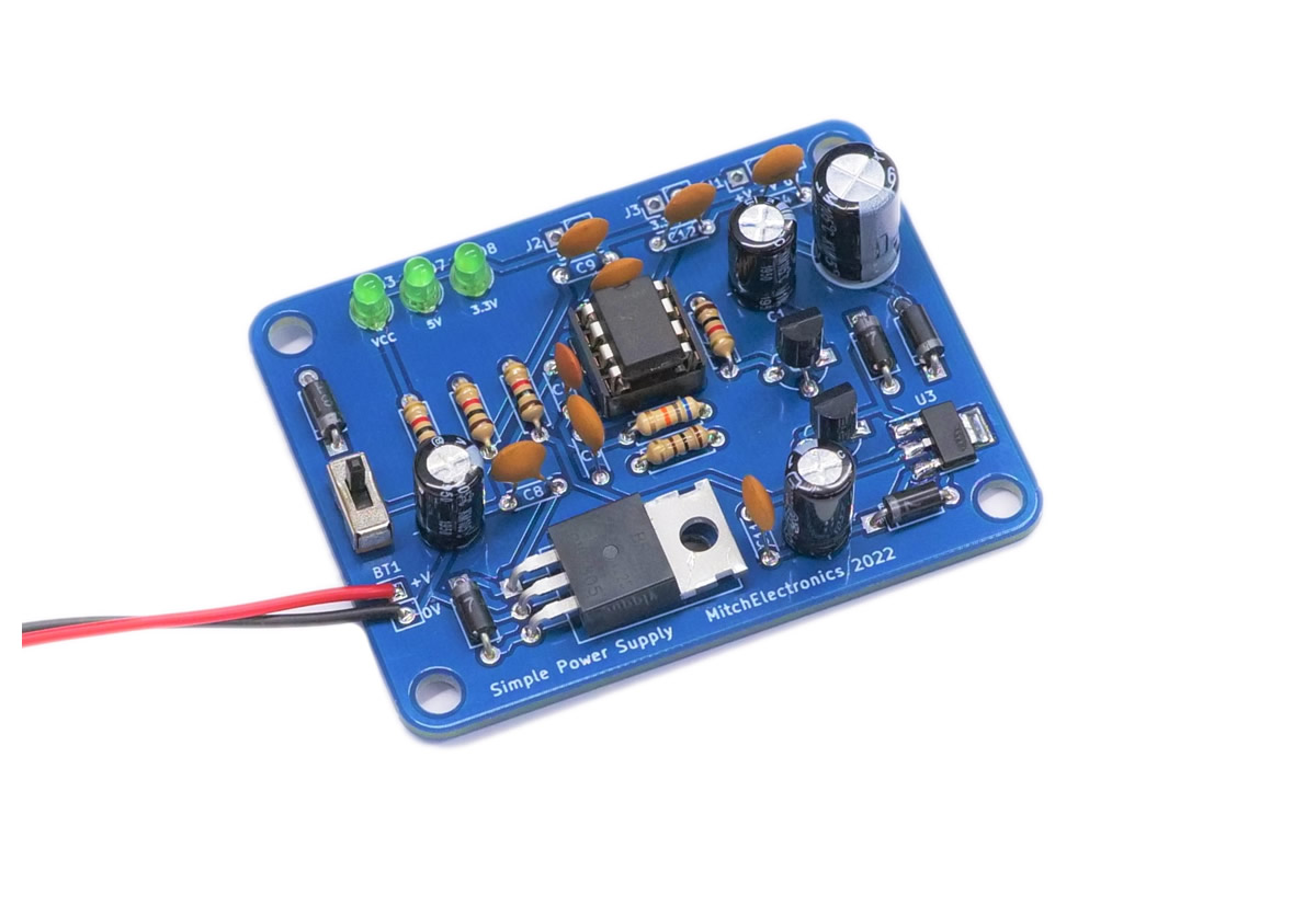
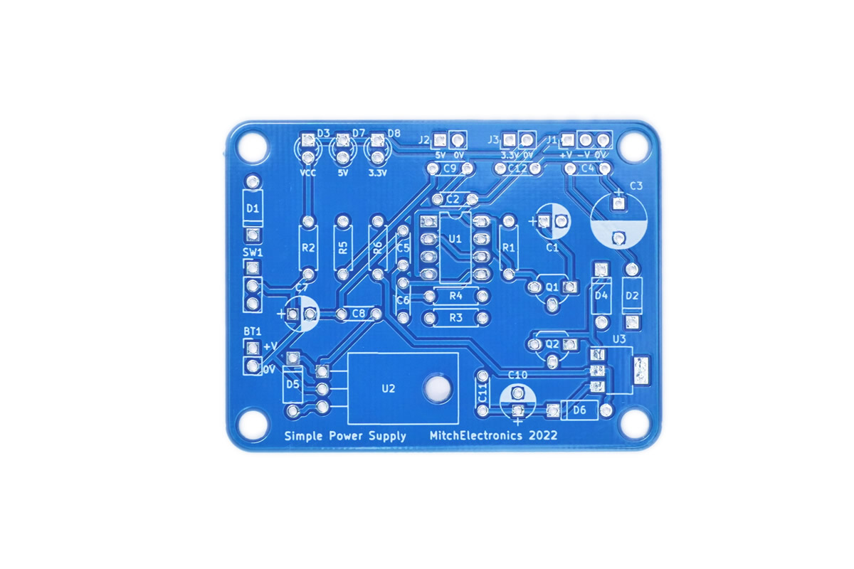
To get around all these problems, the Simple Power Supply takes a single positive 9V input (from a PP3 battery) and produces 9V, 5V, 3.3V, and -9V that can all be used to power external circuits. The Simple Power Supply does have some limitations, but works perfectly for MitchElectronics kits as well as low powered projects!
While many circuits can be powered directly with a battery some are not as easily powered. For example, some MitchElectronics kits require a specific voltage supply such as the 4017 Beacon which needs a 5V source (as the buzzer is rated for 5V operation only). In these scenarios, a power supply circuit is needed which can produce the required voltage and this is where the Simple Power Supply comes in.
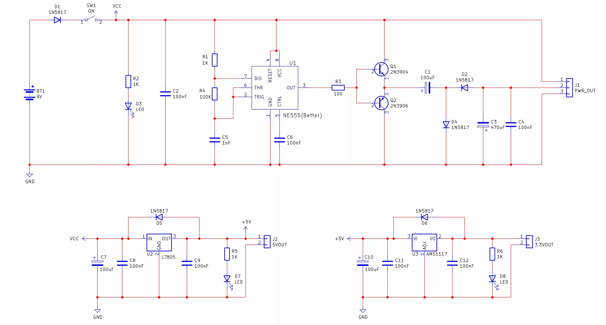
The Simple Power Supply is made up of three main circuits; a negative voltage generator, a 5V regulator, and a 3.3V regulator. The negative voltage generator consists of a 555 astable oscillator that drives a push-pull amplifier (Q1 and Q2) which then drives a capacitor/diode network which converts the square wave pulses into a negative voltage. To learn how this works you can look at the Negative Voltage Generator kit here which describes in detail capacitive coupling! The output of the negative voltage generator produces a negative voltage that is approximately the voltage of the input (in this case, 9V) and this voltage can be used for circuits that require dual rails (such as many op-amp circuits).
The Simple Power Supply also has two fixed voltage outputs which can be used with most modern circuitry; 5V and 3.3V. The 5V is generated with the use of a 7805 regulator IC while the 3.3V is generated with the use of an AMS1117 (some kits may be shipped with the LM1117) which converts the 5V output from the 7805 into 3.3V. Each regulator circuit has as polarised capacitor for smoothing (C7 and C10) and two decoupling capacitors (C8, C9, C11, and C12). Each regulator also has a protection diode that prevents the regulators from being damaged by ESD and other external voltage spikes.
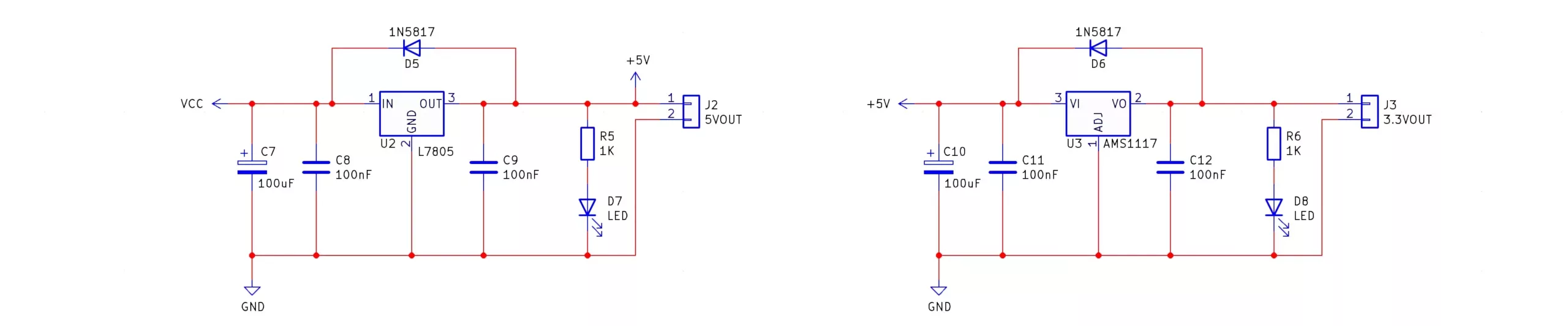
The 3.3V regulator used in this kit is an SMD type which can be tricky to solder however this is intentional. One of the aims of this kit is to show that SMD components can be used in DIY projects and makers should not be dissuaded from using them as some manufacturers are starting to phase out through-hole parts. SMD parts are not only much smaller than their through-hole counterparts but are often cheaper too which makes them a viable solution for DIY enthusiasts.
Note - It is recommended that any power output does not exceed 100mA in current consumption otherwise the regulator supplying the current will get hot!| Component | PCB Reference | Quantity | Looks Like |
|---|---|---|---|
| 8 DIP Socket | U1 | 1 |  |
| 555 Timer IC | U1 | 1 |  |
| 2N3904 NPN Transistor | Q1 | 1 |  |
| 2N3906 PNP Transistor | Q2 | 1 |  |
| 7805 5V Regulator | U2 | 1 |  |
| AMS1117 3.3V Regulator | U3 | 1 |  |
| 1nF Ceramic Disc Capacitor | C5 | 1 | 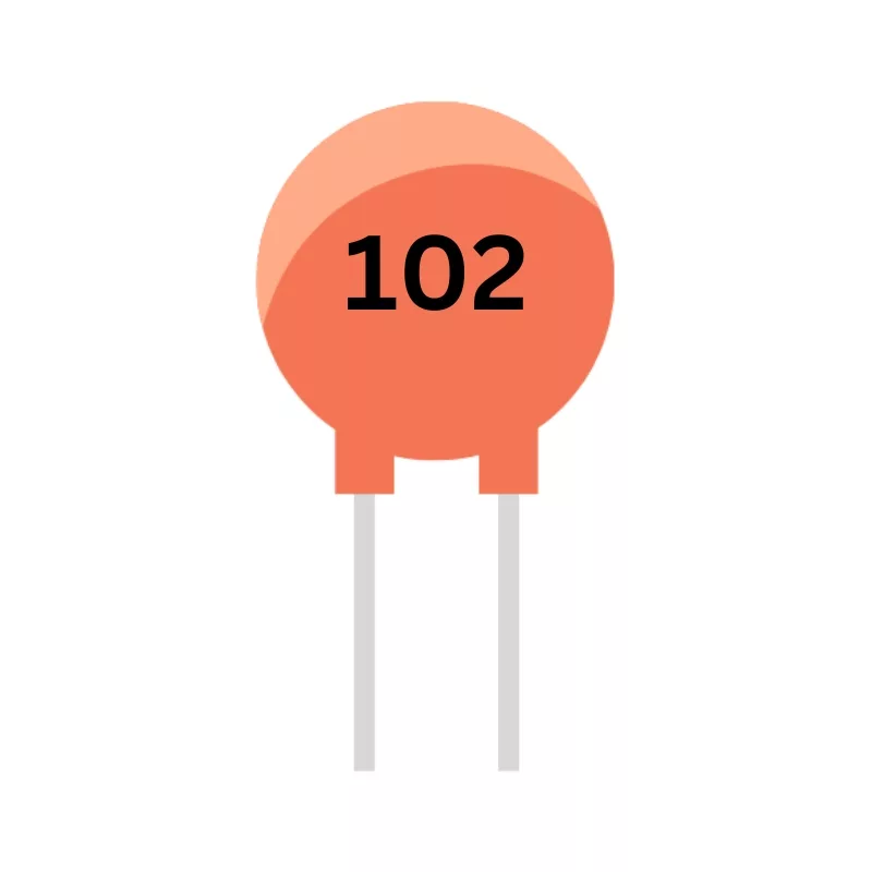 |
| 100nF Ceramic Disc Capacitor | C2, C4, C6, C8, C9, C11, C12 | 7 |  |
| 100uF Electrolytic Capacitor | C1, C7, C10 | 3 | 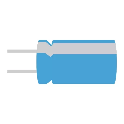 |
| 470uF Electrolytic Capacitor | C3 | 1 |  |
| 100R Resistor | R3 | 1 | 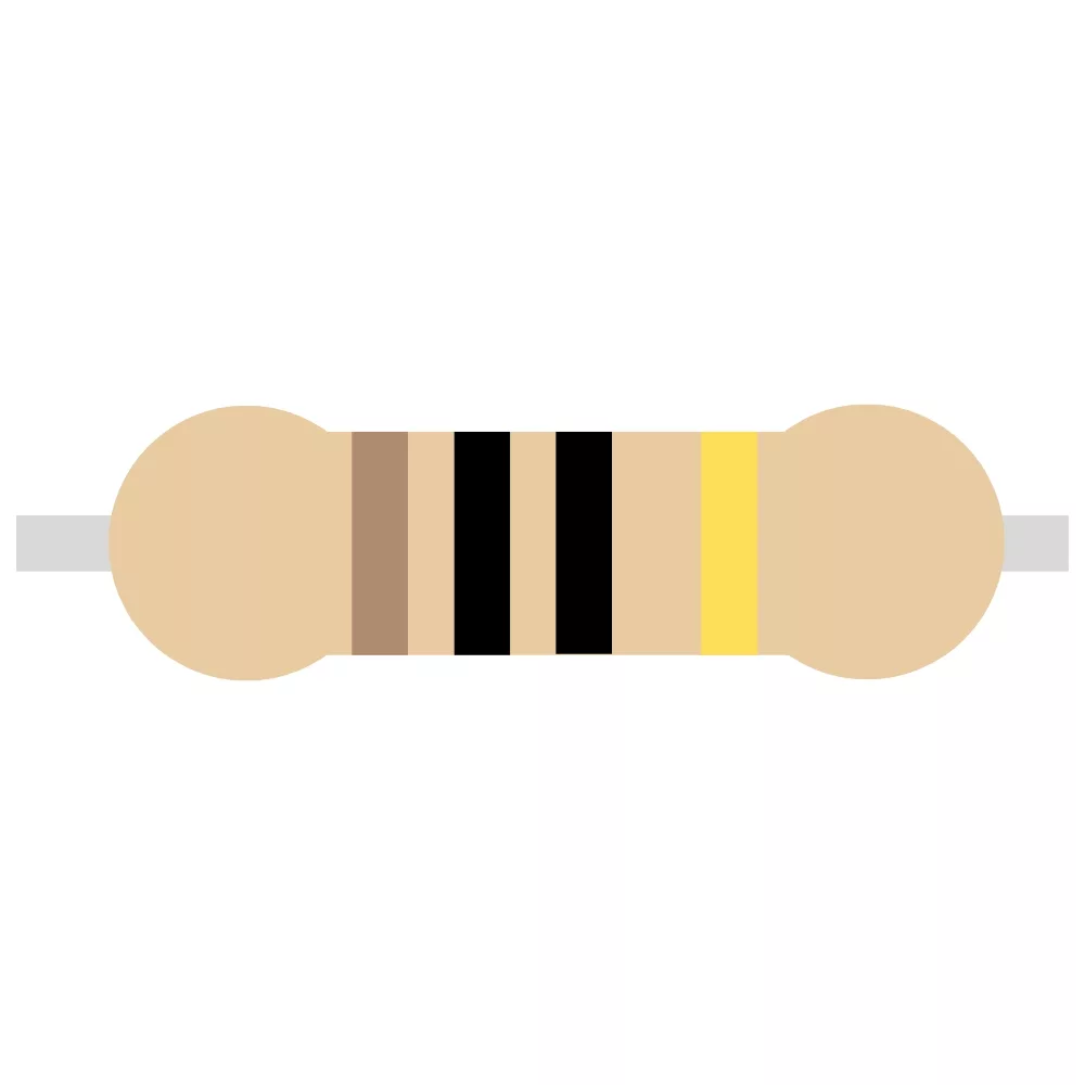 |
| 1K Resistor | R1, R2, R5, R6 | 4 |  |
| 100K Resistor | R4 | 1 | 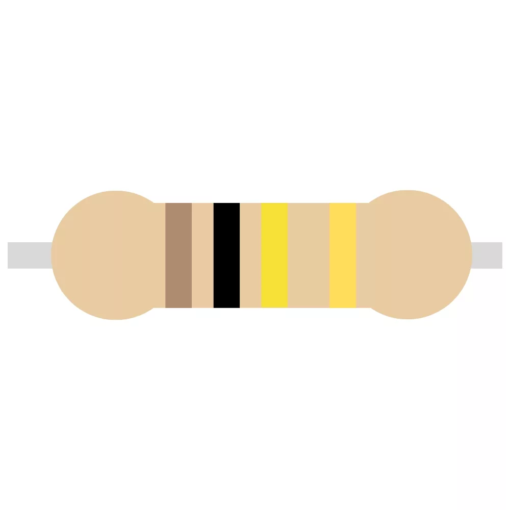 |
| 1N5817 Schottky Diode | D1, D2, D4, D5, D6 | 5 | 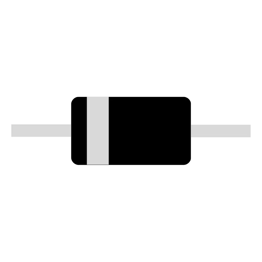 |
| 3mm Green LED | D3, D7, D8 | 3 |  |
| Miniature Slide Switch | SW1 | 1 | 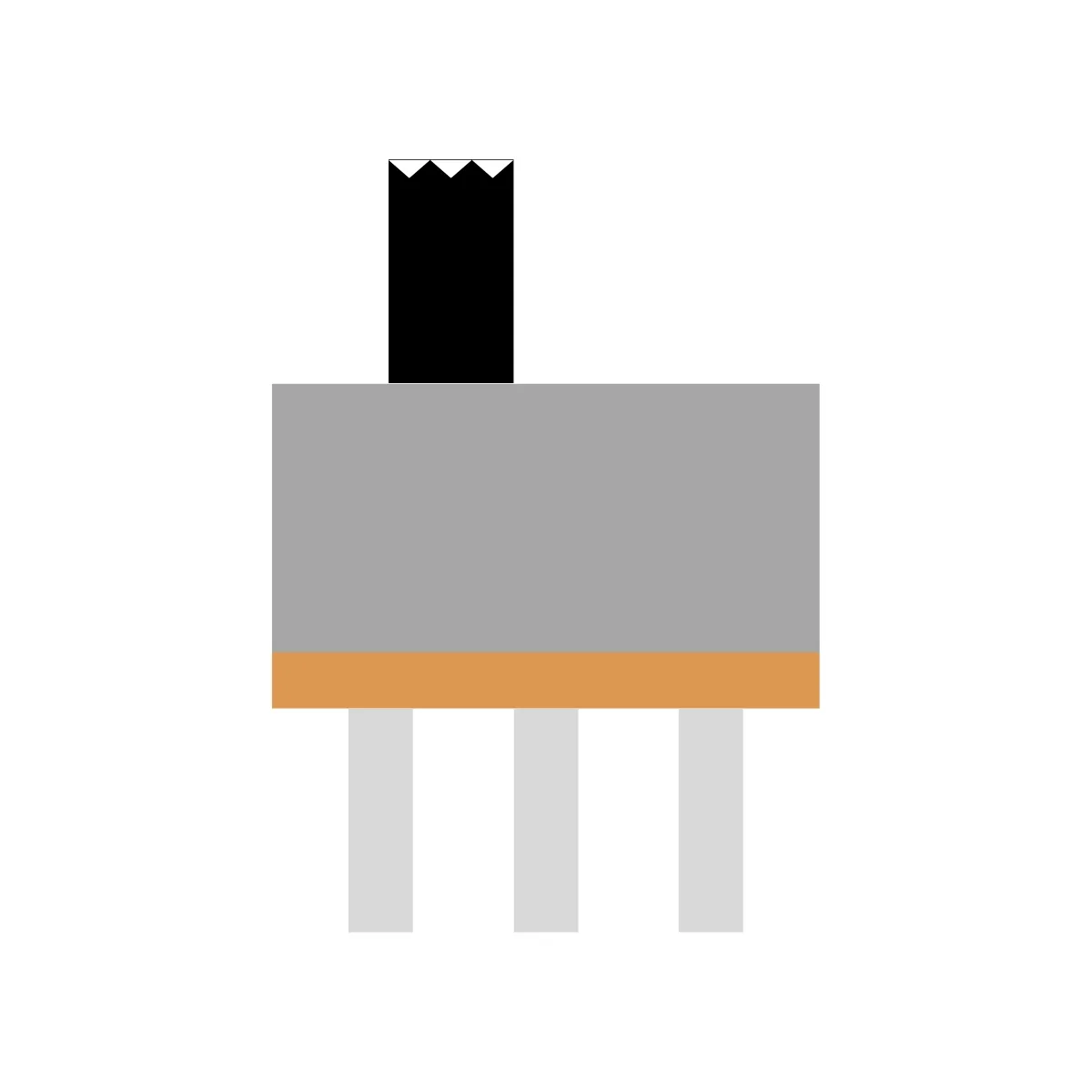 |
| Red Wrire | - | 3 |  |
| Blue Wire | - | 1 |  |
| Black Wire | - | 3 |  |
| PP3 Battery Connector | - | 1 | 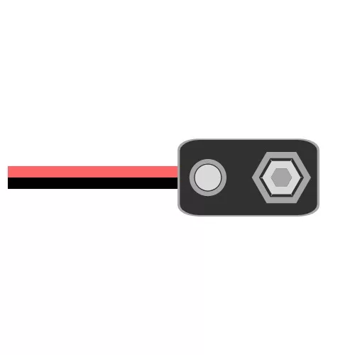 |
If this kit is combined with the AC-DC 5V Regulator kit and a toroid transformer, it's possible to create a fully operational bench power supply that can be used to provide fixed voltages as well as a negative source. Furthermore, a cheap volt and amp meter can be used to measure the power draw from devices, and using fused outputs will protect your circuit from unintentional damage.
Combining the Simple Power Supply with a USB charger and battery bank can create a portable power supply able to power numerous remote projects. If installed into a briefcase along with a multimeter, Raspberry Pi computer, and the Simple Function Generator, a complete portable workshop can be created that allows for remote work.

To learn more about how to solder electronic components, download the Electronics Construction Manual free using the button below
Electronics Construction Manual
When soldering components, it is essential that you do so in a particular order, so that it is easy to add components and get to their legs. Generally, you always start with the smaller components (such as resistors and capacitors), before moving onto the larget parts (potentiometers and ICs).
Soldering Guide
The Simple Power Supply is great for teaching about power conditioning as well as making an ideal candidate for enclosure design
Do not regulate the negative output voltage with a linear regulator. Instead, if regulation of the negative rail is needed, use a switch mode power supply!

(+44) 7516 323 698

27 Willow Way, Meon Vale, CV37 8FT, United Kingdom

Co. House No. 14068499