Siren LFO Synthesiser Instructions

Siren LFO Synthesiser Instructions

Table of Contents

1. Introduction

Check out the VCO Kit before proceeding with this one!

1.1. Pre-learning – The VCO Kit

Before you learn how the LFO Siren Synthesiser works, it is best to first get the VCO kit and learn how that works, as this LFO Siren Synthesiser kit has two VCOs inside it, which make up the core of this project

Binary is a on off signal

1.2 What is the LFO Siren Synthesiser?

The MitchElectronics LFO Siren Kit is a two-stage LFO/VCO circuit that can be used to produce a wide range of tones and patterns including ambulances, fire trucks, warning systems, octave pulses, and much more.

However, there is much more to this kit that strange and annoying sounds, and in this kit, you will not only learn how it works, but why.

LFOs are much slower than audio oscillators

1.3 What is an LFO?

A Low Frequency Oscillator, or LFO, is a special oscillator that focuses on the generation of low frequency oscillations. While oscillators found in musical instruments can be between 50Hz and 44kHz, those found in LFOs will often be less than 1Hz. But what benefits does a LFO provide, and how are they used in the music industry?

Depending on the genre of music you like, you may at times hear sudden variations in a tone, such as a rising note, a wobble, or in the case of Dub Step, the wah-wah of a screeching noise. All of these effects are controlled by LFOs, such as the rate of wobble, the pitch of the note, or the gating of it.

This kit can modulate signals

1.4 How does it differ to the VCO kit?

The MitchElectronics VCO kit is different in that it consists of just a single voltage controlled oscillator stage whose frequency can vary between 20Hz and 40kHz. While this allows it to produce a tone, it isn’t very useful for producing slow changing signals. Furthermore, only the LFO can produce a tone AND change its nature, whereas the VCO can only produce a fixed tone for a fixed input voltage.

Thus, the VCO kit would be used in conjunction with a. keyboard or other musical voltage source, while the LFO Siren is an entire instrument in its own right.4

2. Schematic

3. Simulation

Coming Soon

4. How the Siren LFO Synthesiser work?

Before diving into the exciting world that is the LFO Siren Kit, it is a good idea to get the VCO kit and look through the instructions which can be found here, as this will explain how VCOs work (we will not be covering that here).

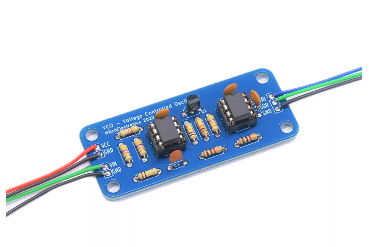
There are several different parts that make the Siren LFO work, but the four most important are the first VCO (acting as an LFO), the adjustment potentiometers, the second tone VCO, and the selection switches.

Starting with the first and most important part, the first VCO (made from U1A and U1B), is the exact same circuit as that found in the VCO kit, with the exception that the input voltage to the VCO is controlled by the potentiometer RV1 instead of an external voltage. This potentiometer is used to change the output frequency of the VCO, but because of the large size of C1, the frequency of oscillation is very slow (all the way from 0Hz to 1kHz), thus making it an LFO. A second potentiometer, RV2, is used to control the output voltage range of the LFO which effectively increases / reduces the amplitude of the output.

Once the LF waveform has been produced, both the triangular and square wave from the oscillator is fed into a selector switch, so you can decide between a rise and fall in output tone, or a sudden switch between two tones. This signal is then fed into a unity gain buffer (U1C), and this output is then fed into a potentiometer RV3, which determines the amplitude of the final output from the whole LFO stage.

This varied amplitude signal from the LFO stage is then combined with the output from another potentiometer RV5. This potentiometer is used to add an offset to the LFO output, so its centre oscillation frequency can be varied. This offset is also key to setting the main tone for the second VCO, meaning that if the first stage LFO was turned off, the offset potentiometer would force the second VCO to produce a specific tone (adjusting the potentiometer will change this tone).

The LFO and offset are added together using the summation amplifier U1D, and the output of this summation stage is then buffered with a unity gain buffer U2A.  By using the buffer, we ensure that the second VCO stage doesn’t affect the performance of our LFO circuit.

The final stage that is used to generate tones is the second VCO, made up of U2A and U2B. Because of the much smaller capacitor (C2), this stage has a much higher frequency, allowing for most audible tones. The input to this VCO is the combination of all the previous stages, meaning that making changes to any of the potentiometers will change the tone,

The final “final” stage is a simple push pull amplifier (Q3 and Q4) which amplifies the output of the VCO so that it can drive a small external speaker.

5. Component List

ComponentPCB ReferenceQuantityLooks Like
14 DIP SocketU1, U22
LM324U1, U22
1nF CapacitorC21
100nF CapacitorC1, C4, C53
100uF CapacitorC31
1K ResistorR5-R7, R13-R156
10K ResistorR20-R223
47K ResistorR2-R4, R8, R10-R12, R178
100K ResistorR1, R9, R16, R18, R195
2N3904 TransistorQ1, Q2, Q33
2N3906 TransistorQ41
100K PotentiometerRV1 - RV54
SpeakerLS11
SwitchSW1, SW22
Red WireLS11
Black WireLS11
PP3 ConnectorBT11

6. PCB

7. Applications

Synths can be made from this kit

7.1 Synthesiser

This kit was born to be a synthesiser, and can be used to produce all kinds of interesting tones. If mounted into a box and given some external controls, this could become a really power and neat tool for those looking to generate unusual tones. This also means that it can be used in live performances.

Use this kit to produce modulations

7.2 Modulator

This kit can also be modified to work at much higher frequencies, and thus be used as a signal modulator. Simply put, the second VCO can act as a carrier wave, while the first stage acts as the modulating signal. This can then be fed into equipment for testing data buses and much more.

Use the LFO synth to produce alarm sound effects

7.3 Alarm

Probably the most practical use for this kit is as a siren generator. If configured correctly via the potentiometers, this kit can be made into an air raid alarm, police siren, fire truck, and much more.

8. Construction Tips

8.1. Electronics Construction Guide

To learn more about how to solder electronic components, download the Electronics Construction Manual free using the button below

8.2. Component Order

Solder the components in this order to keep things simple

  1. Resistors
  2. IC Socket
  3. Capacitors
  4. Transistors
  5. Switches
  6. Potentiometers

Watch out for the PP3 connector!

  • Make sure the red wire is connected to VCC (sometimes V+)
  • Make sure the black wire is connected to 0V (sometimes GND)

Double-check your components BEFORE soldering!

  • MitchElectronics kits use double-sided PCBs with plated through-holes
  • This makes the PCBs extremely strong
  • It also makes de-soldering very hard, so be sure components are inserted correctly