
Interactive electronics resource
555 Astable Kit Instructions
Build, understand and experiment with the classic 555 astable oscillator. This resource covers the circuit schematic, an interactive simulation, the theory behind the 555 timer, component and PCB information, construction guidance, troubleshooting and ideas for taking the circuit further.
Introduction
What is the 555 timer IC?
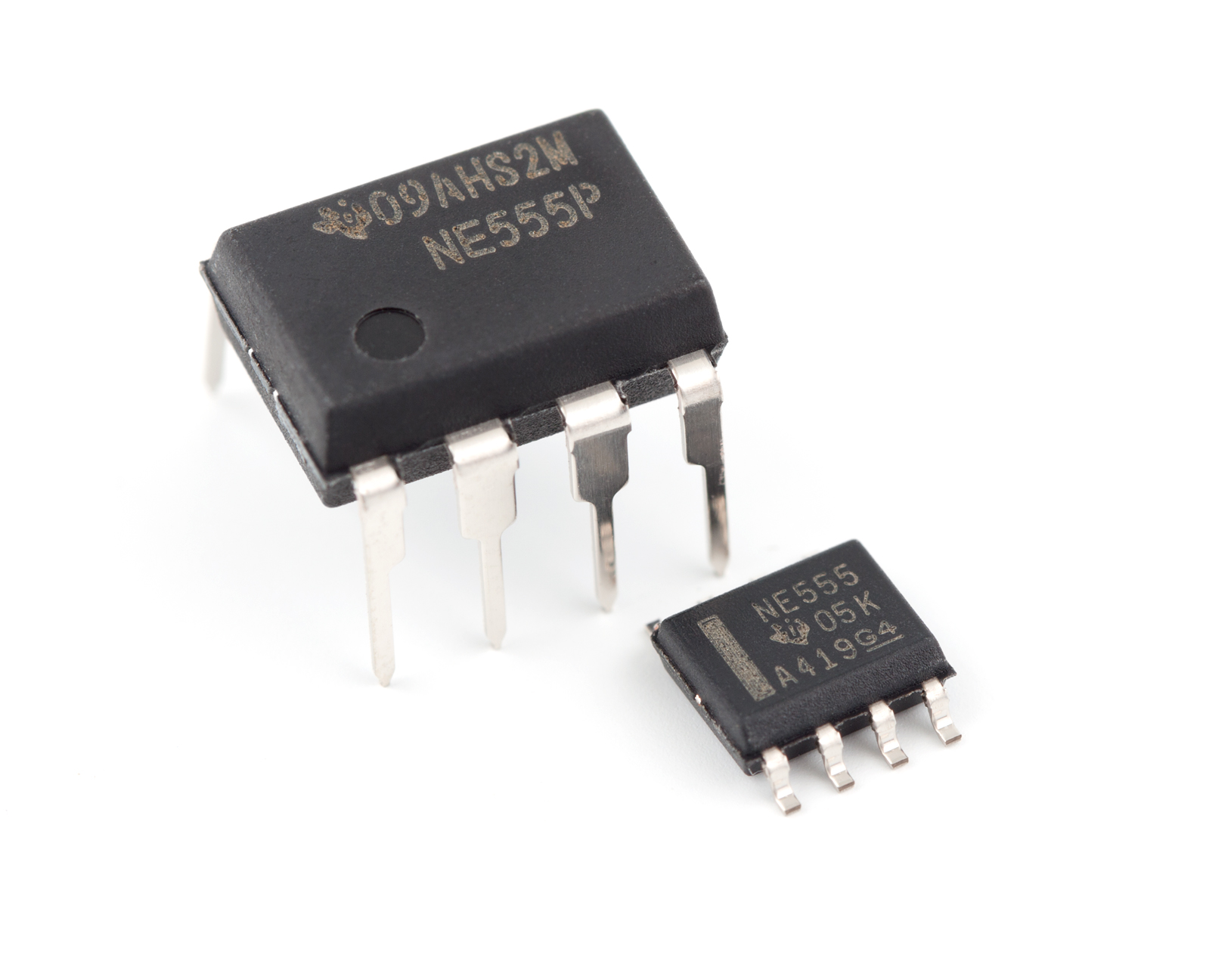
The 555 timer IC is arguably one of the most famous integrated circuits ever manufactured. Despite having been invented in 1972, the 555 remains an extremely popular device and continues to appear in electronics projects and products.
Since the original 555 timer was introduced, many variations have been developed. These include the 556, which contains two 555 timers in a single package, CMOS versions that use less power, and SMD versions that allow the device to be used on much smaller PCBs.
How is the 555 timer IC used?
As the name suggests, the 555 timer is primarily designed as a timer IC. It can be configured to produce a continuous square wave in astable mode, or a one-shot pulse in monostable mode.
The 555 can also be used for many other functions, including digital modulation, latches and PWM generation. These different functions are achieved by combining the internal circuitry of the 555 with external components and different circuit configurations.
Where can you find the 555 timer?
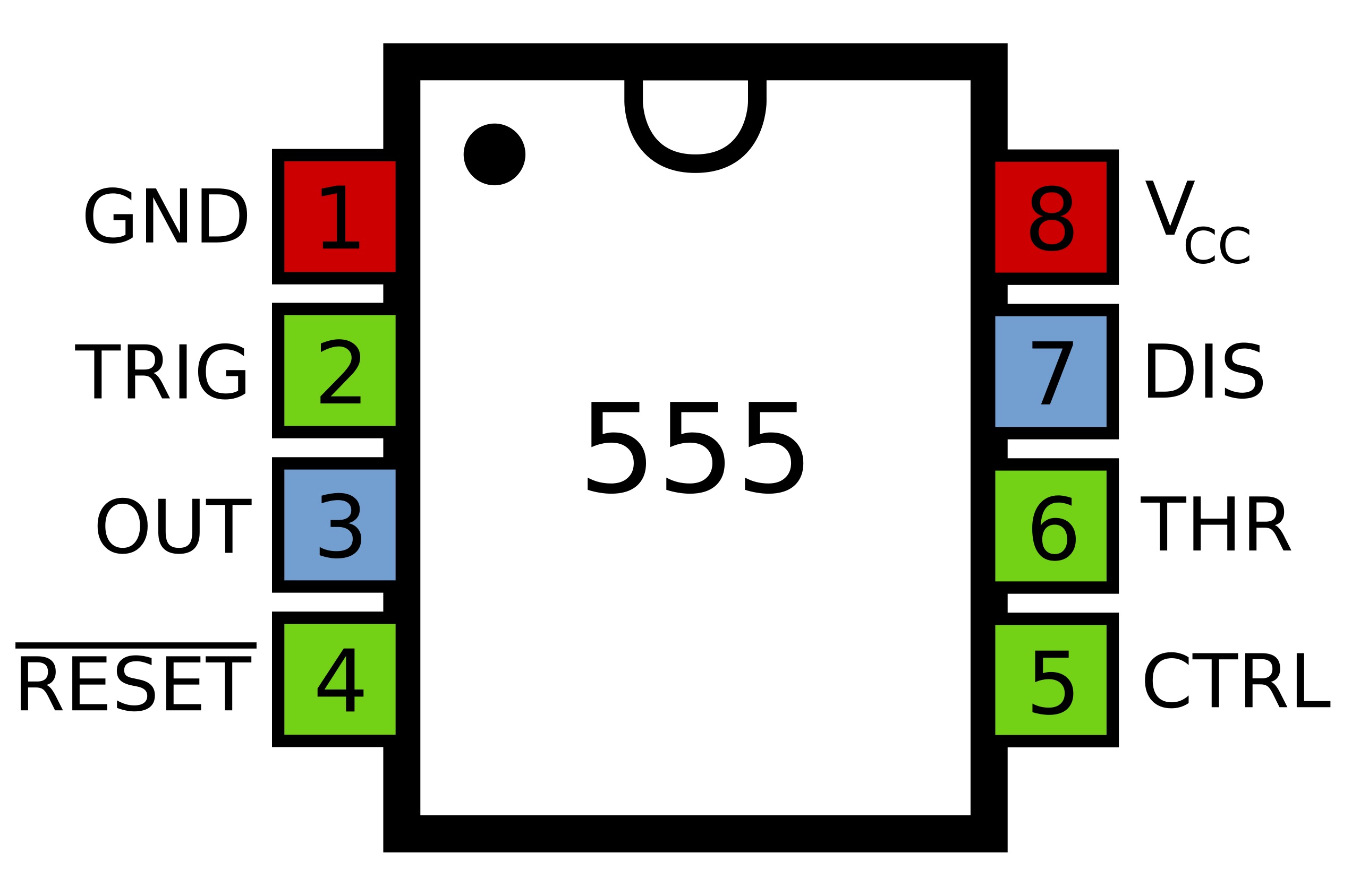
The 555 timer used to be a staple of many electronic circuits, although its use in modern electronics is not always as obvious. Low-cost electronic devices can still use 555 timers for functions such as relay control, flashing indicators and timing.
Its historic popularity also means that the 555 can still be found in older electronic systems that remain in service. If one of these circuits fails, a replacement 555 can often be used to repair it.
Schematic
The schematic below shows the 555 timer configured as an astable oscillator.
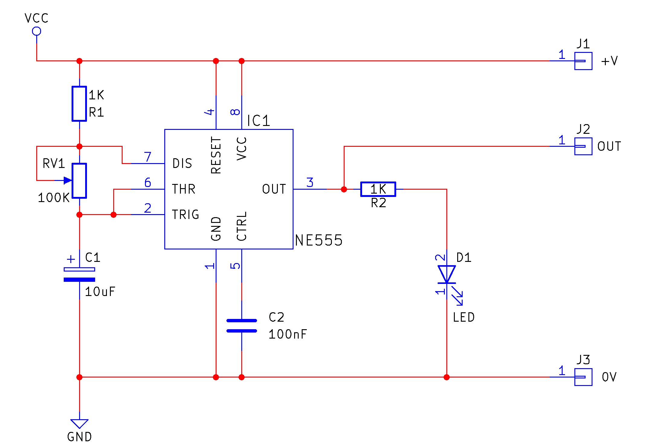
The timing network formed by R1, RV1 and C1 controls how quickly the circuit changes state. The output of the 555 drives an LED, making the oscillation visible as a repeating flash.
How does the 555 Astable work? — Simple explanation
The 555 Astable is a circuit that configures the 555 timer IC to output a square wave that switches between 0 V and VCC, the circuit power supply.
The speed at which this output changes — its frequency — depends on the values of capacitor C1, resistor R1, and potentiometer RV1.
Simply put, the 555 timer charges and discharges capacitor C1 while R1 and RV1 act as a throttle.
If the resistance of R1 and RV1 is low, the capacitor can charge and discharge quickly. The output therefore changes state more quickly and the circuit operates at a higher frequency.
If the resistance is increased, the capacitor charges and discharges more slowly. The output therefore switches more slowly and the circuit operates at a lower frequency.
Turning RV1 gives you a direct and visible way to experiment with the oscillator: change the resistance and the LED flashing rate changes with it.
Timing relationship
A commonly used approximation for a 555 astable oscillator is:
f ≈ 1.44 / ((R1 + 2R2) × C)In this kit, the variable resistance provided by the potentiometer allows the timing resistance to be changed while the circuit is operating. The important practical relationship is simple: more resistance means a slower oscillation, while less resistance means a faster oscillation.
How does the 555 Astable work? — Advanced explanation
Looking at the internal circuit diagram of the 555 timer, several important blocks can be seen:
- Three 5 kΩ resistors, which form the internal reference divider and give the 555 its name.
- A flip-flop.
- Two comparators.
- An inverter connected to the output.
- An NPN discharge transistor.
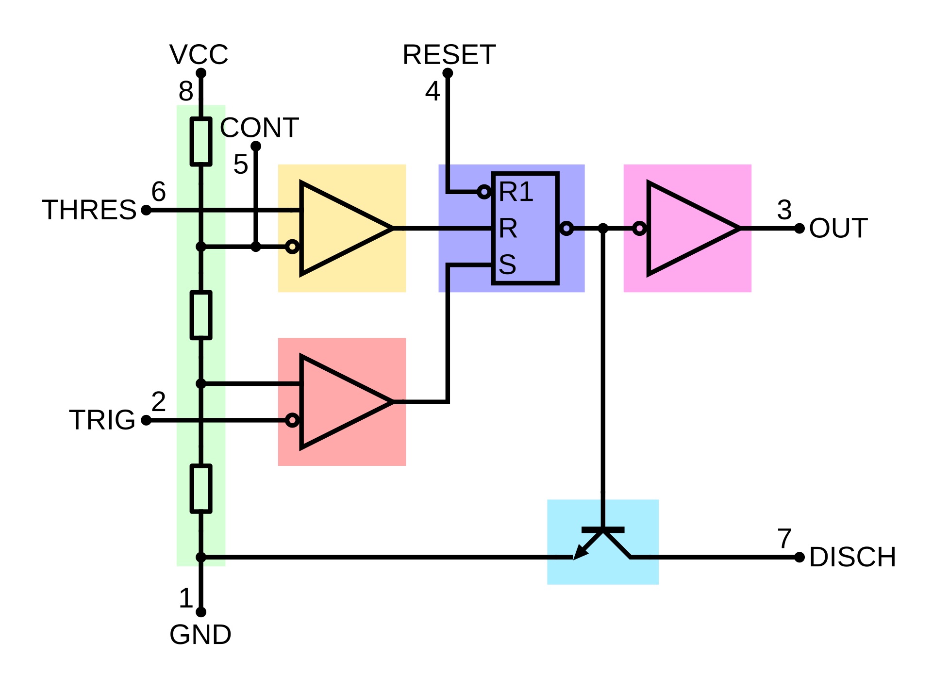
Initially, the voltage across capacitor C1 is 0 V. This also makes the voltage presented to the lower comparator 0 V.
The comparator reference is derived from the internal chain of three 5 kΩ resistors. These create the familiar 1/3 VCC and 2/3 VCC switching levels used by the 555.
At the start of the cycle, the capacitor voltage is below 1/3 VCC. The comparator changes the state of the flip-flop, the output becomes active, and the discharge transistor is switched off.
With the discharge transistor off, capacitor C1 begins charging through R1 and potentiometer RV1. As the capacitor charges, the voltage across it gradually rises.
The upper comparator monitors the capacitor voltage against the 2/3 VCC reference.
Eventually, the voltage across the capacitor rises beyond 2/3 VCC. The upper comparator changes state and resets the flip-flop. This changes the output state and switches the discharge transistor on.
With the discharge transistor on, the capacitor begins discharging through the timing network and the discharge pin towards ground.
The capacitor voltage then falls.
Eventually, it drops below 1/3 VCC. The lower comparator changes state again, the flip-flop changes state, the discharge transistor switches off, and the capacitor begins charging once more.
The process repeats continuously:
- C1 charges.
- The capacitor reaches the upper threshold.
- The 555 changes state.
- C1 discharges.
- The capacitor reaches the lower threshold.
- The 555 changes state again.
- The cycle repeats.
This circuit is described as astable because it has no stable output state. It continually moves between its high and low states while power is applied.
The output of this kit is connected to an LED, so the changing output can be seen directly as the LED turns on and off.
What does the potentiometer do?
The time taken for the capacitor to charge and discharge depends on R1 and the resistance selected by RV1.
Increasing the potentiometer resistance increases the time required for the capacitor voltage to move between the switching thresholds. The LED therefore flashes more slowly.
Decreasing the potentiometer resistance reduces the charge and discharge time. The LED therefore flashes more quickly.
This makes the kit useful not only as a circuit to build, but also as a practical demonstration of RC timing and the internal operation of the 555.
Project ideas
Once the basic circuit is working, its square-wave output can be used as the starting point for several other projects.
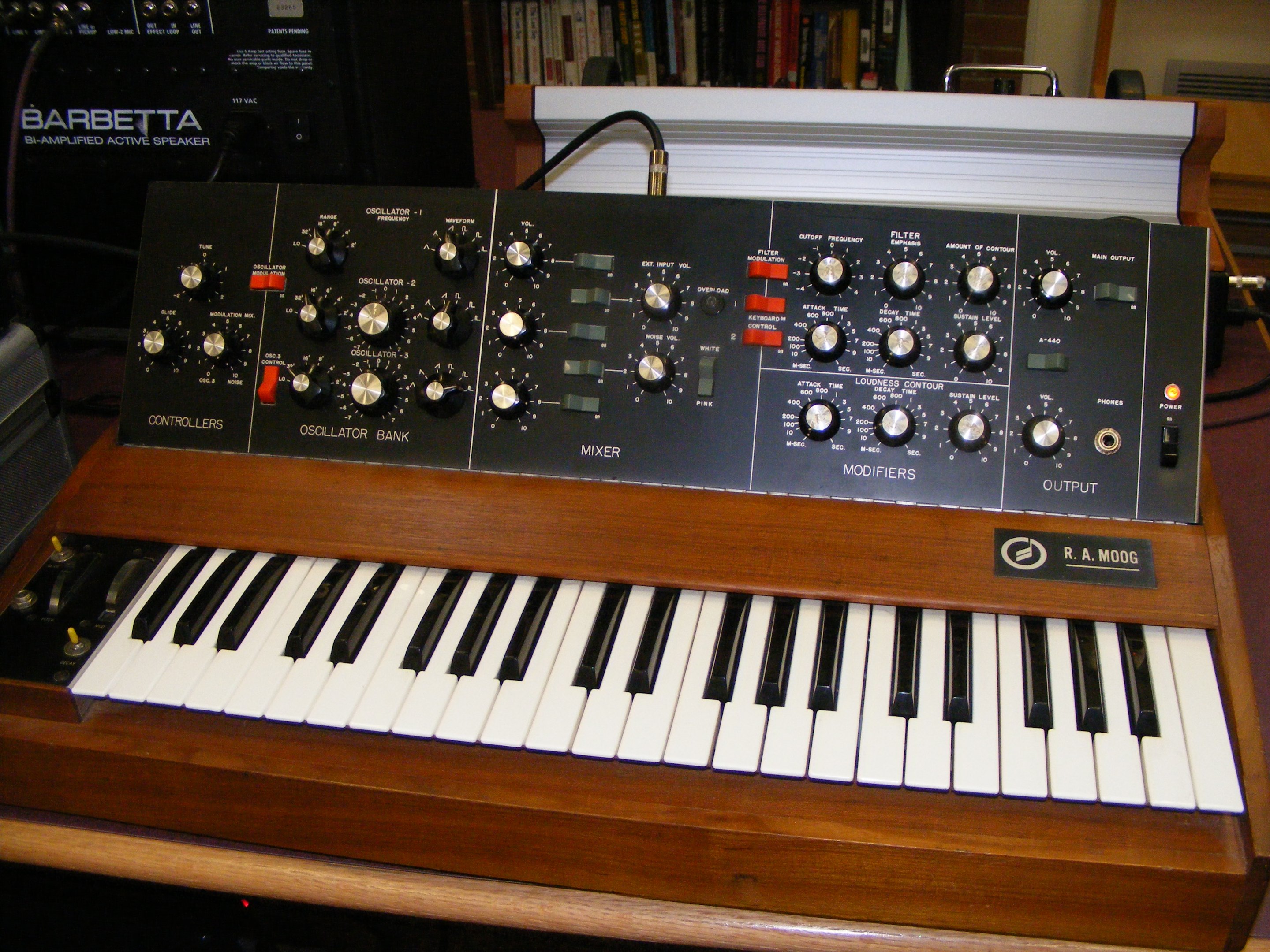
Basic synthesiser
The 555 astable circuit can be connected to an audio amplifier to produce a tone. The frequency of that tone depends on the position of the potentiometer, allowing the circuit to be used as a very basic synthesiser.
The output can also be connected to additional analogue stages such as filters and delays to create more interesting audio effects.
Clock source
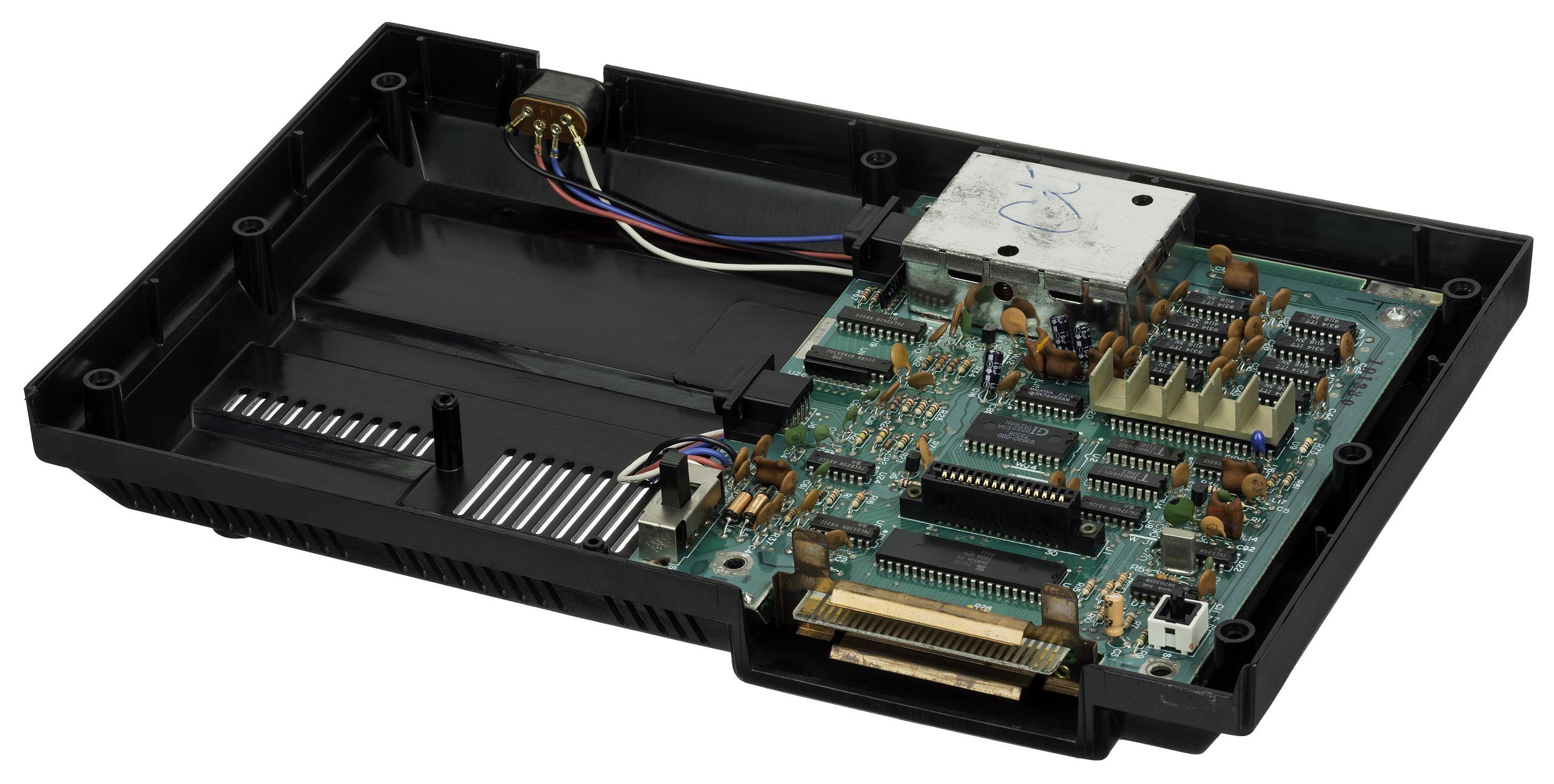
Some projects require a repeating digital clock source, and the 555 astable can provide one.
Although the square wave produced by a basic 555 astable is not necessarily symmetrical, many digital circuits can still use it as a clock signal.
One example is a 4017 Johnson counter light chaser. The 555 provides the repeating clock pulse and the 4017 uses those pulses to advance through a sequence of outputs, allowing a row of LEDs to illuminate one after another.
Indicator
A simpler use for the 555 astable is as a flashing indicator.
For example, a bicycle could use a three-position switch to select left, right or off. Two flashing circuits connected to orange indicators could then provide an automotive-style direction indicator effect.

Going further
Once you understand how R1, RV1 and C1 affect the timing, try experimenting with different component values.
Changing the resistors or capacitor changes the frequency range available from the oscillator. This allows the same basic circuit to be adapted for applications ranging from slow flashing indicators to much faster clock or audio signals.
A useful experiment is to change only one timing component at a time and observe how the circuit behaviour changes.
Try it yourself
Circuit simulation
Not available in mobile view
What you need
Component List
| Component | Quantity | PCB Reference |
|---|---|---|
| 8-pin DIP socket | 1 | IC1 |
| 555 timer IC | 1 | IC1 |
| 100nF ceramic capacitor | 1 | C1 |
| 10uF electrolytic capacitor | 1 | C2 |
| 1K resistor | 2 | R1, R2 |
| 100K linear potentiometer | 1 | RV1 |
| 3mm red LED | 1 | D1 |
| PP3 battery connector | 1 | — |
| 555 Astable PCB | 1 | — |
Inspect the board
Interactive BOM
Board reference
PCB & assembly
The PCB silkscreen provides the component references needed when assembling the kit. Compare the component reference with the component list before soldering each part.
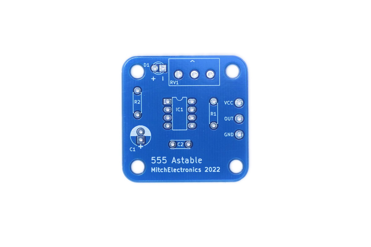
Before soldering
Check the orientation of any polarised components and the 555 timer before fitting them.
It is much easier to correct an incorrectly positioned component before it has been soldered into the PCB.
Inspect the completed board
Before applying power:
- Check that every component is in the correct position.
- Check the orientation of the IC and any polarised components.
- Inspect the underside of the PCB for solder bridges.
- Look for joints that have not flowed correctly.
- Confirm that no component leads or loose wire fragments are shorting adjacent pads.
Build with confidence
Construction tips
Recommended build order
When soldering components, it is useful to work from the physically smallest components to the largest. This keeps the board accessible while it is being assembled and makes component leads easier to reach.
A practical build order is:
- Fit resistors and other low-profile components.
- Fit small capacitors and links.
- Fit the IC socket, if supplied.
- Fit larger capacitors.
- Fit the potentiometer and other controls.
- Fit the LED and remaining connectors.
- Insert the 555 timer only after the soldering work around its socket is complete.
- Inspect every solder joint before applying power.
Electronics construction guide
If you are new to soldering or electronic kit construction, use the MitchElectronics Electronics Construction Guide alongside these instructions.
The construction guide explains how to identify components, prepare them for fitting, solder them correctly and inspect the finished PCB.
Component order
Component order matters because larger components can make it harder to reach the pads for smaller parts.
As a general rule, start with components such as resistors and small capacitors before moving on to taller parts such as potentiometers, connectors and ICs.
For additional guidance, see the general soldering resources:
When it does not work
Troubleshooting
The LED does not flash
Start with the simple checks:
- Confirm that the power supply is connected with the correct polarity.
- Check that the 555 timer is fitted in the correct orientation.
- Check the LED orientation.
- Confirm that R1, RV1 and C1 are fitted in the correct positions.
- Inspect the PCB for missed solder joints or accidental solder bridges.
The LED remains permanently on or off
If the output is stuck in one state, concentrate on the timing network.
Check the connections around R1, RV1 and C1 and inspect the pins associated with the 555 timing and discharge circuit.
A missing connection, incorrect component position or solder bridge can prevent the capacitor from repeatedly charging and discharging.
The potentiometer does not change the flashing rate
Check that RV1 is soldered correctly and that all of its required connections reach the timing network.
Also inspect R1 and C1. The frequency depends on the complete timing network, so a fault elsewhere in that network can make the potentiometer appear to have no effect.
The circuit behaves erratically
Inspect the board carefully for poor solder joints, loose component leads and solder bridges.
If possible, compare the finished PCB with the PCB reference image and schematic one connection at a time rather than changing several components at once.
Ready to experiment?
Once the circuit is working, do not stop at simply watching the LED flash.
Turn the potentiometer and observe how the frequency changes. Then consider changing the timing resistor or capacitor values to create a different frequency range.
The 555 astable is a simple circuit, but it demonstrates several important electronics concepts at once: RC timing, comparator thresholds, feedback, digital switching and adjustable oscillation.
Feeling brave? Try changing the resistor and capacitor values and see how far you can push the oscillator.