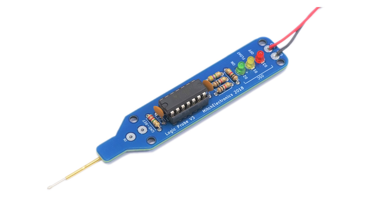


Testing circuits can be done with multi-meters and oscilloscopes but this is not always the best method. For example, not everyone has access to an oscilloscope and multi-meters are no good for fast-changing signals. Another reason is the ease of use, testing a circuit with an oscilloscope can be tricky as you need to probe the contact and then turn away to look at the display. All it takes is for the probe to slip slightly and then the oscilloscope will be showing the signal trace for a completely different connection.
This is where the faithful logic probe saves the day! Instead of having numbers to show voltages or a display to show signals over time the logic probe has just three LEDs for outputs. These outputs can show on, off, floating, and oscillating! So long as the probe has a common ground to the circuit under test (which can be done easily by either using the same power supply or connecting the probes GND-REF to the circuit’s ground), the probe will display one of the four listed conditions above when the probe contact is connected to a point in the circuit. But how does this probe work? Get this kit and find out!
The Logic Probe is an ideal project for those who are building their own low-cost functional equipment while also providing a project. The use of a spring-loaded pogo pin makes the Logic Probe suitable for testing sensitive equipment while providing a secure probe connection between the circuit under test and the probe itself. The Logic Probe can be built in 3o minutes making it ideal for use in the classroom, and the in-depth documentation enable learners to understand how the logic probe works as well as how to construct it.
Note that product specifics such as output frequency depend on the tolerance of the components. The numbers provided here are an approximation only. Also take note that the estimated delivery is not guaranteed (unless special delivery is chosen) and free delivery has a maximum waiting time of two weeks. Any product that is returned which is built using lead solder is ineligible for a refund.
All parts sold by MitchElectronics are compliant with RoHS and REACH directives which ensure that they can be used in commercial environments as well as complying with environmental laws. Watch the video below to learn more about RoHS compliance and why it may be important for your next DIY project!
For full terms and conditions for all MitchElectronics products, click the button below.